Contents
User’s Guide
Servicing North America
For immediate technical or application assistance
Servicing Europe
Unpacking Instructions
Model No Description
Page
Unpacking Instructions Chapter General Description
Contents
General Description Introduction
Features OS531 OS532 OS533 OS534
OS530HR OS530L-CF
Features OS523 OS524
Front of the Thermometer
Parts of the Thermometer
Display Details Key
OS530 Series Handheld Infrared Thermometer Rear View
Rear of the Thermometer
General Description
Ac Power Operation
Battery Operation
OS530/OS520 Series with Built-in Laser Sighting
Operating the Thermometer
Field of View OS531, OS532, OS530L
Field of View OS534, OS523-1
Field of View OS523-2
10 Field of View OS524
Trigger
Measurement Techniques
11 Recorder Hookup
If the trigger is pulled two times in rapid sequence
Real Time Mode Active Operation
Recall Mode
13. Visual Function Flow Chart
Using the Lock Function
Adjusting Emissivity
Calculating Temperature Values
Changing the Temperature from F to C or vice versa
Turning on the Display Backlighting
Thermocouple Input OS532, OS533, OS534
If you are not in High Alarm Display Mode HAL when
Using the Alarm Functions
To set the low alarm value OS533, OS534, OS523, OS524
To disable this mode, press the key again Icon disappears
One Stop Bit
Key to decrement the printing interval.
System Requirements
Irtempsoft
Connecting the IR-System to the PC
Using the Handheld Infrared Thermometer
Storing the Temperature Data on Command OS534, OS523, OS524
Erasing the Temperature Data from Memory
Mode
Recall Mode Passive Operation
Functional Flow Chart Recall Mode
Reviewing the Last Parameters
AMB temperature MEM location
PRN F
Using the Handheld Infrared Thermometer
Laser Sighting
Rear View
Description
Laser Dot
Operating the Laser Sighting
Lines of Sight of the Laser Sighting and Thermometer
Sighting Scope
Installing and Operating the Sighting Scope
Installing the Sighting Scope
Maintenance Replacing the Batteries
Safety Warning
Cleaning the Lens
Calibrating the Thermometer
Servicing the Laser Sighting
Problem Solution
Troubleshooting Guide
Problem
If you see an error code, either
Target are offset by design
Specifications
Specifications are for all models except where noted
OS533, OS534, OS523, OS524
No Laser Sighting 17 hours continuous
Laser Sighting
Glossary of Key Strokes
Glossary of Key Strokes
Appendix How Infrared Thermometry Works a
Thermal Radiation
Blackbody
Calculating Temperature
Optics Field of View
Appendix Emissivity Values
Metals
Material Emissivity ε
Nonmetals
Appendix Determining an Unknown Emissivity
Figure C-1. Determining Emissivity
Figure C-2. Determining Emissivity with a Drilled Hole
Appendix Determining an Unknown Emissivity
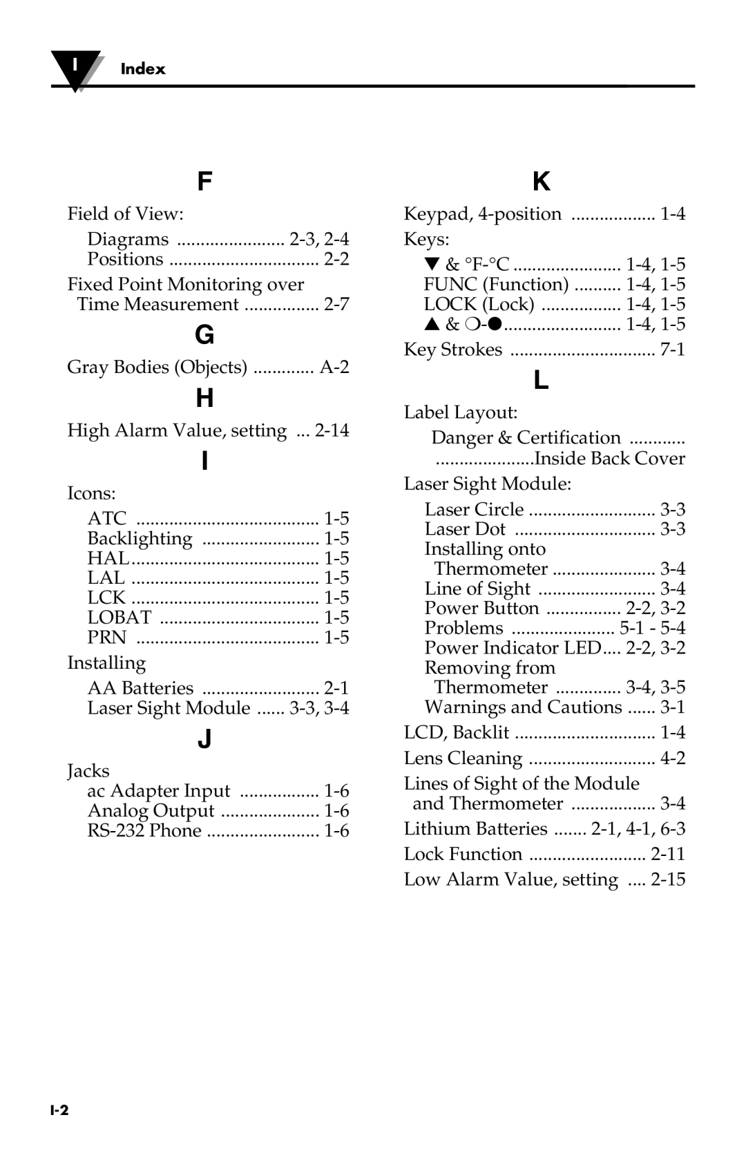
Index
Field of View Diagrams
Recall
WARRANTY/DISCLAIMER
PH/CONDUCTIVITY
Shop online at omega.com
