2Using the Handheld Infrared Thermometer
2.4.1Reviewing the Last Parameters
°F
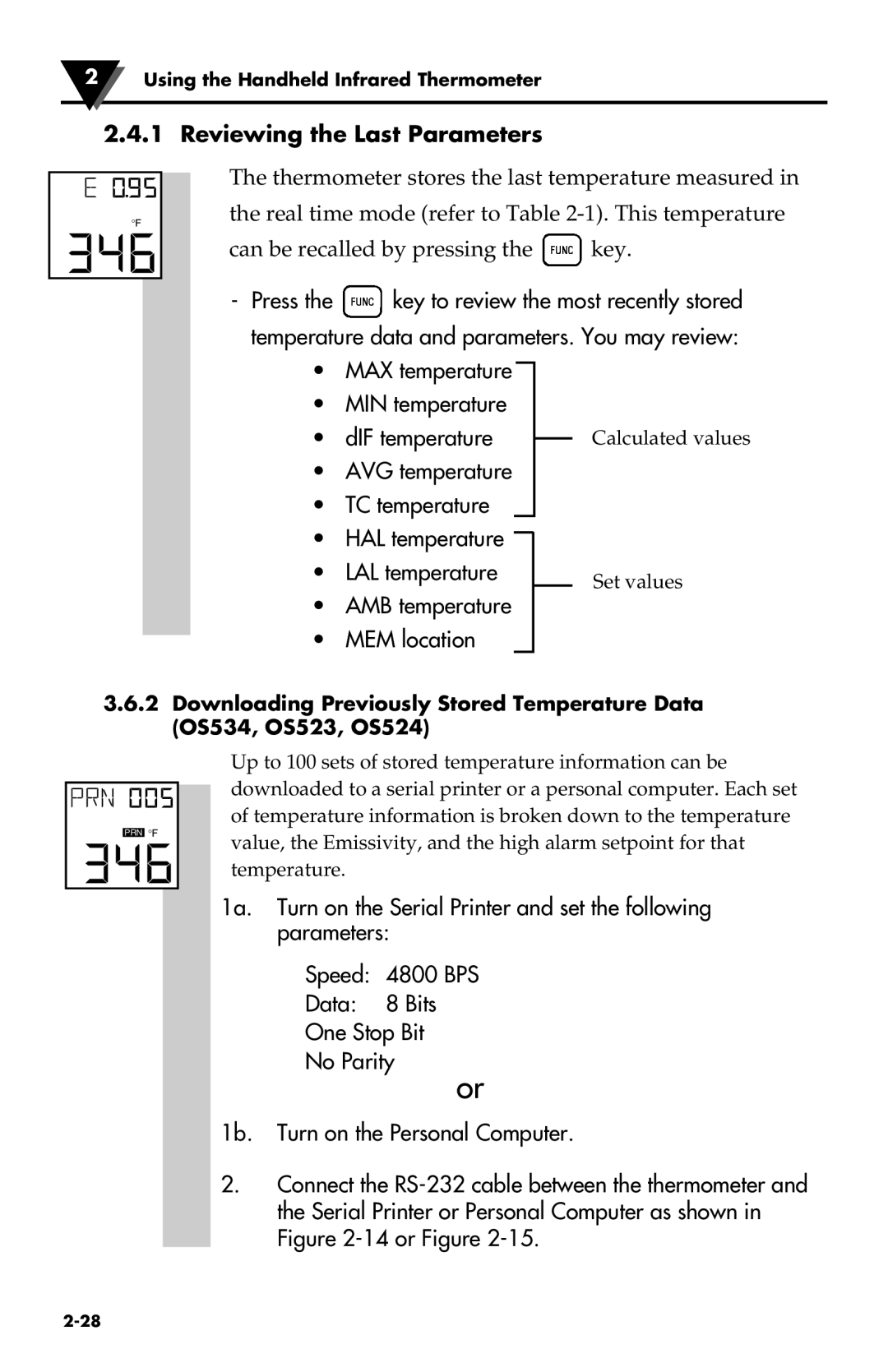
The thermometer stores the last temperature measured in the real time mode (refer to Table
can be recalled by pressing the ![]() key.
key.
-Press the ![]() key to review the most recently stored temperature data and parameters. You may review:
key to review the most recently stored temperature data and parameters. You may review:
•MAX temperature
•MIN temperature
• dIF temperature |
| Calculated values |
|
•AVG temperature
•TC temperature
•HAL temperature
• LAL temperature | Set values |
|
•AMB temperature
•MEM location
3.6.2Downloading Previously Stored Temperature Data (OS534, OS523, OS524)
PRN °F
Up to 100 sets of stored temperature information can be downloaded to a serial printer or a personal computer. Each set of temperature information is broken down to the temperature value, the Emissivity, and the high alarm setpoint for that temperature.
1a. Turn on the Serial Printer and set the following parameters:
Speed: 4800 BPS
Data: 8 Bits
One Stop Bit
No Parity
or
1b. Turn on the Personal Computer.
2.Connect the