Operating Instructions
Digital HD Video Cassette Recorder
For your safety
How to replace the fuse
ANY 13 AMP Socket
Operating precaution
Contents
General and Features
Features
Multi-functional interfaces
Menu-driven setup
Time codes
Channel high-sound-quality digital audio
Controls and their functions
Front panel
Front Panel Top Section
Front Panel Centre Section
INT/EXT switch
TC/CTL switch
TC/UB switch
TAPE/EE switch Stop mode
Jog mode
REMOTE/LOCAL switch
SHTL/SLOW switch
Remote lamp
PREVIEW/REVIEW buttons
Preroll button
Auto Edit button
A IN/SET/OUT a OUT buttons
Dvcpro format 25 Mbps/50 Mbps cassette play display lamp
Counter display area
Cassette inserted display lamp
SCH lamp
Monitor Select switches
Headphones jack
Volume control
` Metre FULL/FINE selector switch
Diag button
Front Panel Bottom Section
SET button
Indicated on the Warning screen are the warning
Signal GND terminal
Connector area
Power mains socket
Fuse holder
CUE in connector
Time Code in connector
Time Code OUT connector
CUE OUT connector
SD REF OUT connector
? SD REF in connectors and 75-ohm termination switch
HD REF OUT connector
Digital Audio IN/OUT connector
Operations using the front panel bottom controls
Items which can be registered
Registration method
Example of the menu displayed for registering VTR statuses
When registering setup menu items
When registering VTR statuses
Press it
Cancel button This is for cancelling the reset operation
Cancel button
Are reset to the factory settings
Prog Menu 1 to 4 buttons
Operations using the front panel top controls
VTR status displays
Registered menu item displays
How to change a registered menu setting
Entering the setting
Cancelling the change
VTR status item table
Name of registration
Menu item
Description of display
Set the Control switch on the front panel to Local
Connections
Composite Video OUT3
Tapes
Switching on the power/inserting the cassette
Cassette
STOP/STAND by mode
Still Timer Setting
Lights and the tape stops travelling
Recording
1Selecting video/audio input signals
2Adjusting the audio level
Level controls Pushed in unity value
Playback
Jog mode Shuttle mode
Jog/shuttle
Select the editing channel
Select the editing mode
Manual editing
For insert editing
Preroll
Automatic editing
Deck to deck
When the unit is used as the player
Switch settings and adjustments
When the unit is used as the recorder
Set the Power switch to on
Selecting the editing mode
Entering the edit points
Match frame processing function
Negative duration function
Checking the edit points
Calculating the duration
1Resetting both the edit in and OUT points
2Resetting either the edit in or OUT point
Modifying the edit points
Preview
Retry function
Executing automatic editing
Postroll
Auto tag editing
Review
Deleting the edit points
Audio split editing
Entering the edit points
Modifying the edit points
Duration display
Displaying the audio split edit points
Cueing up the tape to the edit points
Operations
Normal mode
Expansion mode execution using the MODE/SEL button
Expansion mode selection status
Expansion mode selection status
Editing channels
Selecting the Multi CUE mode
Multi CUE function
Registering the cue points
Description of displays
Mode display
Search display Display mode selection mark
Operations
Example of LED display
Search point and registration point operations
Search point operations
¢ 1 on
# CUE
Operations on the same selected page page Mode = Manu
Registering cue points
# CUE 7 # CUE
¢¢ appears as the registration pointer display
Deleting registered points
When registering cue points using numbers
Resetting the registration points individually
Search operations
Outline
IC Card mode selection
IC Card function
IC Card
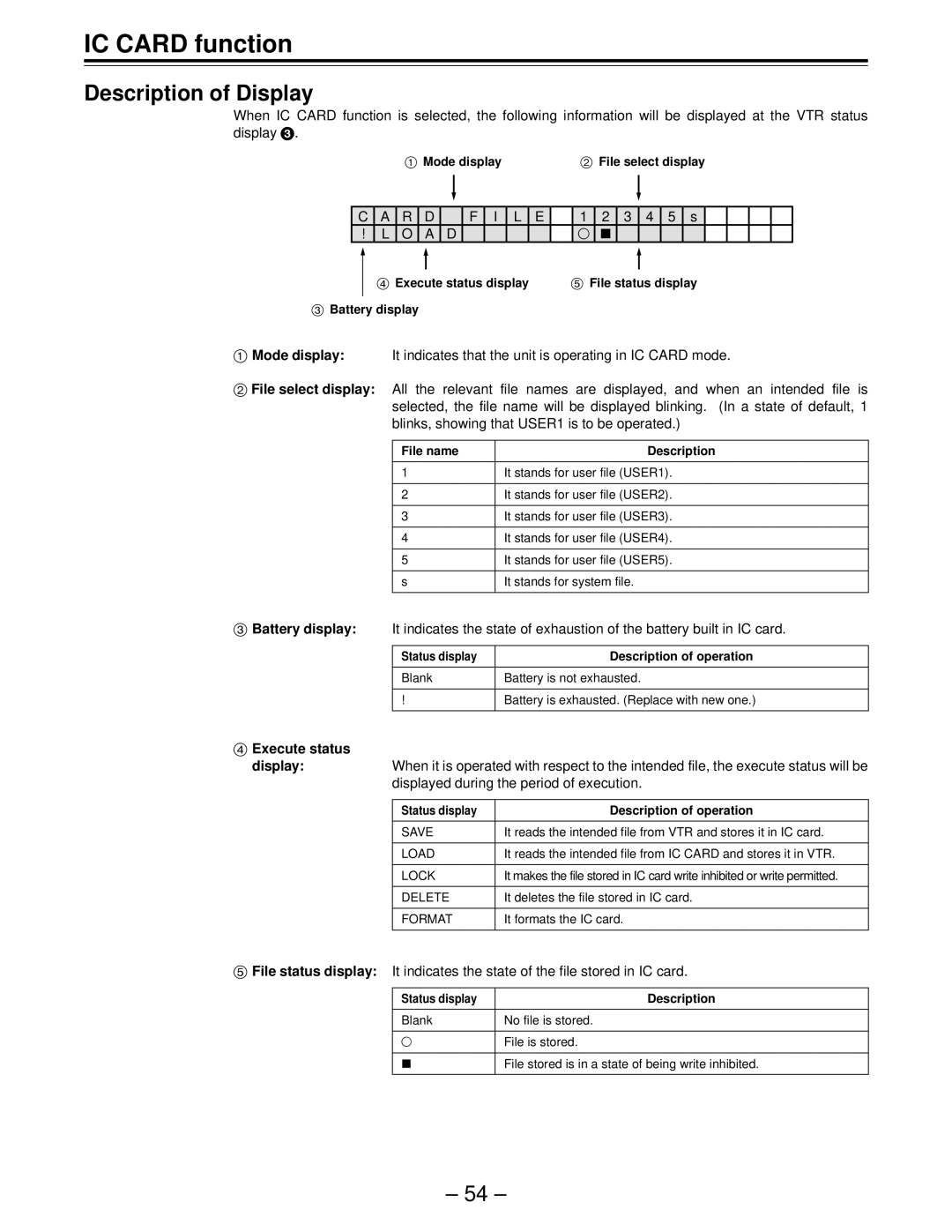
Description of Display
Execute status Display
Displayed during the period of execution
File selection
Description of Operation
3 4
F O M a
Variable memory function
Variable memory playback operation procedure
Variable memory mode selection
Variable memory function
Variable memory editing operation procedure
Setup menu No.015 Auto Step
Error LOG function
Error LOG mode selection
Description of Menu
Are displayed
Operation mode display
Description of Operations
Time code display
Search dial should be used in jog mode if at all possible
Setup default settings
Changing the settings
SETUP-MENU Init SET YESPLAY/NOSTOP
System User
Setup menus
Changing the file
Each user file contains the following items
Setting and releasing the lock mode
Press the Menu button
Turn the search dial and move the cursor
Settings can be locked
Loading a user file
Except No. A00 Load and No. A01 Save
Automatic loading of user file when the power is turned on
Saving a user file
Control matrix of the adjustments is shown below
Setting Description
Video output signal adjustments
System menu
VO SYS
SYS H
SYS SC
SDI SYS
0200 100
+ The audio output phase is delayed from the video output
0100
Menu
User menu
Basic
MDY
Display
YMD
DMY
Manual
Format in tape playback
SYS Format
Manual Dvcam
Hdref
OUT REF
Input
Sdref
Operation
Memory stop function
REC INH
FRZ Mode
SOF&EJ
Lamp
Rota Mode
Mode
Interface
IN/OUT
Local 50P
Master
Port
Setting
Edit
Postroll
JOG FWD
JOG REV
Edit
RPLCE4
CH1+CH2
Rplcec
Tape Protect
Time Code
SBC sub code data area
Vaux video auxiliary data area
Video
ENH
HD SDI OUT
Video OUT
SD SDI OUT Video OUT
ADD20L
ADD22L
ADD21L
AUT O
Line
Audio
Digi
AES
CH7
CH5
CH6
CH8
AUD
CH1 CUE
Fade
MIX L
Linear
MON Auto
Moni CH
AUTO11
Moni SEL
REC PT
AUD VR
Menu
User bit
Time code/user bit
Time code
Alone. In addition,
Setting the internal time code
Setting the external time code TC switch
Recording internal/external time codes
Place the unit in the stop mode Set the TC/CTL button to TC
Reproducing the time code/user bit
Characters displayed
Operation mode
Superimpose screen
Display position
Audio recording channel
Recording track Recording signal
Audio recording channel and monitor output selection
Monitor output channel
Rack mounting
Rack-mounting adapters
Video head cleaning
Maintenance
Condensation
Displaying the Diag menu
Error messages
Diag menu
This display the VTR information
Priority Display Description
Displaying the Hours Meter information
Item No Description
Priority Monitor display
Stop
Table of Auto OFF Error messages
Counter display Monitor display
Eject
If an abnormal torque applied to the supply reel motor
For
If the supply reel motor should rotate at an abnormally
Is detected or if an abnormal current flowing to
RS-232C interface
Hardware specifications
External interface specifications
Introduction
Protocol
Software specifications
Outline of send procedure from controller
Communication parametres
Return format VTR
Error code table
When the communication has terminated abnormally Nack
ACK
Supplementary notes
Command table
Commands relating to operation control Notes
Operation Message
Standby STX OBF ETX
STX OSR ETX
Reverse
OFF Standby STX OBN ETX
Commands relating to inquiries Notes
Send command
Operation
Microsoft QuickBASIC sample programme
CLS
Pin No Signal
Connector signals
Pin No. Signal
Signal Pin No
Signal
RS-232C Remote 25-pin D-SUB crossover cable supported
Pin No
Audio Input This sets the CH1 audio input
Printed circuit board
F1 board
Impedance SW
Video Output Connector
Specifications
Video input connector
YES
Digital Audio
Audio Input Connector
Audio Output Connector
Cue Track
Panasonic Broadcast Europe
Panasonic Broadcast Europe GmbH
Hagenauer Str , 65203 Wiesbaden-Biebrich Deutschland Tel