Names and Functions of Parts
The illustrations shown may differ from the actual physical appearances.
|
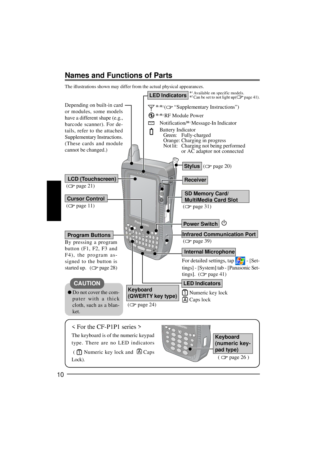
| LED Indicators | *1 Available on specific models. | |
|
| *2 Can be set to not light up( page 41). | ||
Depending on | *1*2 ( “Supplementary Instructions”) | |||
or modules, some models | *1*2 RF Module Power | |||
have a different shape (e.g., | ||||
Notification/*1 | ||||
barcode scanner). For de- | ||||
tails, refer to the attached | Battery Indicator | |||
Supplementary Instructions. | Green: | |||
Orange: Charging in progress | ||||
(These cards and module | ||||
Not lit: Charging not being performed | ||||
cannot be changed.) | ||||
or AC adaptor not connected | ||||
|
| Stylus ( page 20) | ||
LCD (Touchscreen) | Receiver | |||
( | page 21) |
|
| |
Cursor Control | SD Memory Card/ | |||
MultiMedia Card Slot | ||||
( | page 11) | ( | page 31) | |
|
| Power Switch | ||
Program Buttons
By pressing a program button (F1, F2, F3 and F4), the program as- signed to the button is started up. (![]() page 28)
page 28)
CAUTION
![]() Do not cover the com- puter with a thick cloth, such as a blan- ket.
Do not cover the com- puter with a thick cloth, such as a blan- ket.
![]() Infrared Communication Port
Infrared Communication Port
( | page 39) |
| |
Internal Microphone |
| ||
For detailed settings, tap | - [Set- | ||
tings] - [System] tab - [Panasonic Set- | |||
tings]. ( | page 41) |
| |
LED Indicators |
| ||
Keyboard | Numeric key lock | |
(QWERTY key type) | ||
Caps lock | ||
( page 24) | ||
|
< For the CF-P1P1 series >
The keyboard is of the numeric keypad type. There are no LED indicators
( ![]() Numeric key lock and
Numeric key lock and ![]() Caps Lock).
Caps Lock).
Keyboard (numeric key- pad type)
( ![]() page 26 )
page 26 )
10
