How to wire the remote controller

(1)

Turn OFF the power and remove the ceiling panel


air-intake grille. (Refer to 3-6-1 Before Installing the


Ceiling Panel in the Installation Instructions supplied


with the indoor unit.)

(2)

Remove the 3 power box cover screws and 2 control


box cover screws, then remove both covers. At this


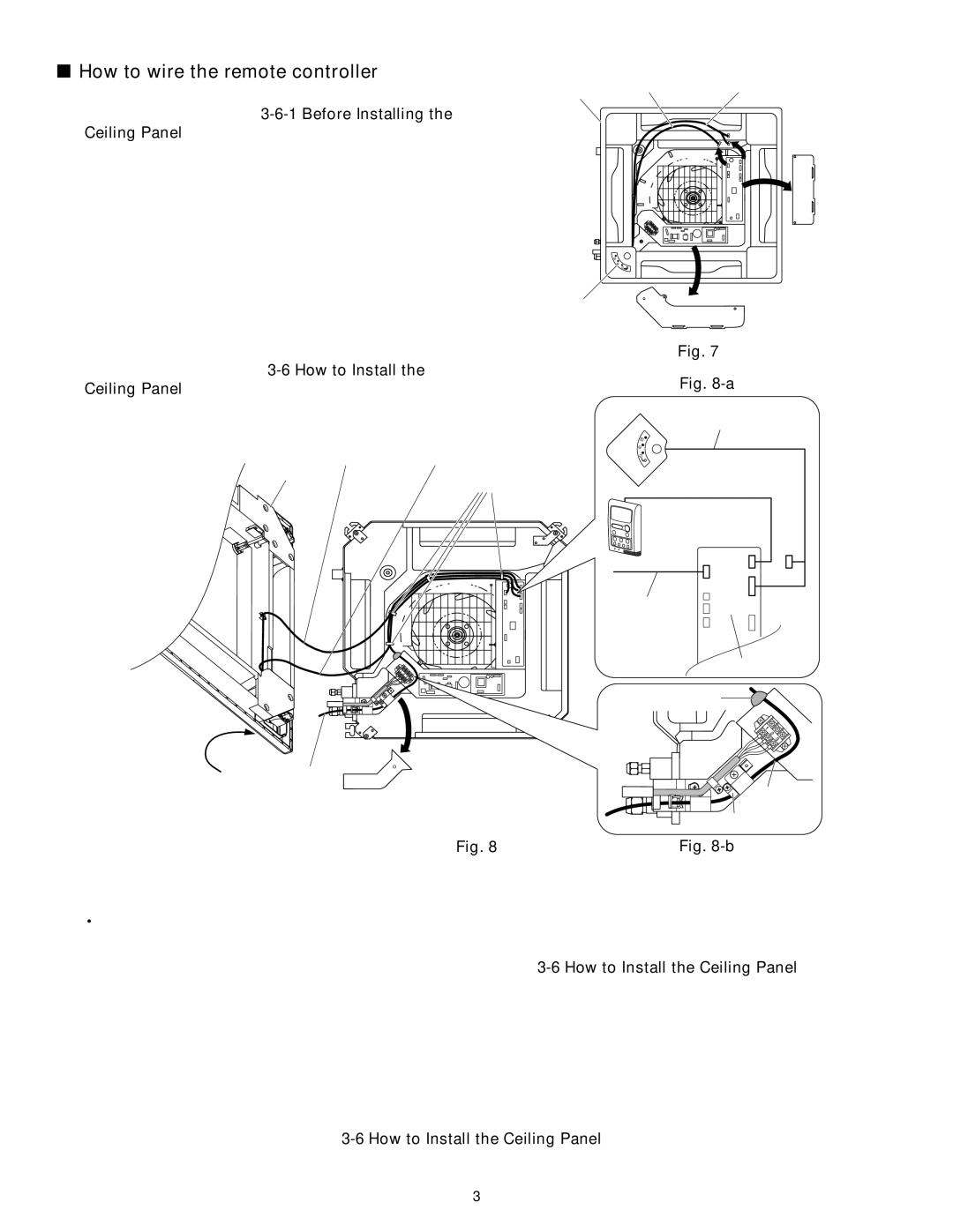
time, take care not to drop the covers. (Fig. 7)

Ceiling


5P FLAP


7P IND and 4P RC


wiring connector


wiring connector

panel


(3) Disconnect the 7P (IND) terminal and 4P (RC) termi-

nal of the 7P IND and 4P RC wiring connectors and

the 5P terminal of the 5P FLAP wiring connector

from the control box PCB connectors (IND, RC,

FLAP). Disconnect each wiring connector from the

clamp that fastens it. (Fig. 7)

Indicator

Control box cover

Power box cover

(4) Remove the ceiling panel. (To remove the ceiling

panel, follow the steps for 3-6 How to Install the

Ceiling Panel in the reverse order. Refer to the

Installation Instructions supplied with the indoor unit.)


5P FLAP


7P IND and 4P RC


Ceiling


wiring connector


wiring connector


panel


Clamps


Fig. 7


Fig. 8-a


Indicator


7P IND and 4P RC


wiring connector


Wire harness


Remote


4P

controller


FLAP

IND RC


5P FLAP


7P

wiring


connector


Control PCB


Putty


Terminal cover

Wire harness

Indicator

Wire harness

Clamping strap

Fig. 8

Fig. 8-b

(5)Remove the terminal cover screws, then remove the cover. At this time, take care not to drop the cover. (Fig. 8)

(6)Pull in the wire harness from the remote controller as shown in Fig. 8-b.

‡Remove the putty before wiring. After wiring, make sure to restore the putty.

(7)Insert the wire harness 4P terminal into the control box PCB connector (RC). (Fig. 8-a)

(8)Install the terminal cover. Then install the ceiling panel. (Refer to 3-6 How to Install the Ceiling Panel in the Installation Instructions supplied with the indoor unit.)

(9)Insert only the 7P (IND) terminal of the 7P IND and 4P RC wiring connector into the connector (IND) on the control box PCB. Store the 4P terminal inside the control box. (Fig. 8-a)

(10)Next, insert the 5P terminal of the 5P FLAP wiring connector into the connector (FLAP) on the control box PCB. (Fig. 8-a)

(11)When the connections are completed, fasten the wire harness and each wiring connector with the clamps.

(12)Install the power box cover and control box cover.

(13)Install the air-intake grille. (Refer to 3-6 How to Install the Ceiling Panel in the Installation Instructions supplied with the indoor unit.)

3

Page 111
Image 111
Panasonic CZ-18BT1U, CS-MKE9NB4U, CU-4KE31NBU, CU-4KE24NBU, CU-3KE19NBU, CS-MKE12NB4U How to wire the remote controller

CZ-18BT1U, CS-KE18NB4UW, CS-MKE12NB4U, CU-3KE19NBU, CU-4KE24NBU specifications

The Panasonic CS-KE18NB4UW and CU-KE12NK1, along with the CS-KE12NB41, CZ-18BT1U, and CU-KE18NKU, represent a suite of advanced air conditioning solutions built with cutting-edge technologies designed to provide optimal comfort, energy efficiency, and air quality in various settings.

One of the standout features of this lineup is the inverter technology. Inverter air conditioners adjust the compressor speed to maintain the desired temperature efficiently. This leads to significant energy savings compared to traditional air conditioners, which tend to frequently cycle on and off, consuming more power. By continuously regulating the temperature, the Panasonic units not only save electricity but also prolong the lifespan of the compressor.

Another noteworthy characteristic is the nanoe™ technology integrated into some of these models. Nanoe™ technology uses hydroxyl radicals to purify the air, minimizing harmful bacteria and allergens. This makes the Panasonic units particularly suitable for users with allergies or respiratory issues, providing a cleaner and healthier indoor environment.

In terms of design, these models are sleek and compact, allowing them to fit seamlessly into any room decor, whether in a home, office, or commercial space. The quiet operation is another advantage, making them ideal for bedrooms and study areas where minimal noise is essential.

Furthermore, the CS-KE18NB4UW and CU-KE12NK1 offer a range of powerful cooling and heating capacities, making them versatile solutions for various climate conditions. The cold climate performance ensures consistent heating in colder regions, while the robust cooling capabilities make them perfect for hot summer months.

The user-friendly features include a smart remote control system, allowing users to adjust settings with ease from a distance. Some models are equipped with Wi-Fi capability, enabling integration with smart home systems for enhanced control and programmability.

In conclusion, the Panasonic CS-KE18NB4UW, CU-KE12NK1, CS-KE12NB41, CZ-18BT1U, and CU-KE18NKU air conditioning units exemplify innovation and efficiency. With their inverter technology, air purification features, compact designs, and smart functionalities, they stand out as ideal choices for maintaining comfortable and healthy indoor environments throughout the year.