Front (Explanation)
VCR-ON/OFF button (]/I)
Press to switch the VCR from on to standby mode or vice versa. In standby mode, the unit is still connected to the mains.
Edit Terminal switch
By connecting a video movie camera or VCR with an EDIT socket via an Edit cable, various kinds of editing functions can be performed more quickly and efficiently between two VCRs or between a VCR and a video movie camera.
DV Input/Output socket [DV1/DV2(¥)]
To connect the DV cable to digital video equipment with iEEE
“¥” is the logo marked on products conforming with the “i.LINK” specifications. For further details on the DV terminal, refer to the Glossary of Terms on page 58.
Edit Mode switch
PLAYER: When this VCR is used as the playback VCR during editing operations.
RECORDER: When this VCR is used as the recording VCR during editing operations.
≥Normally set at this position.
PASSIVE: When operating this VCR using another VCR or an editing controller.
AV1 21-pin Scart socket [AV1 (TV)]
This
The scart terminal is also called “Peritel”, “Euro Connector” or “Euro AV”.
13 5 7 9 11 13 15 17 19 ![]() 21
21
| 2 | 4 | 6 | 8 | 10 | 12 | 14 | 16 | 18 | 20 |
NORMAL (AV1/AV2) |
|
| ||||||||
1 | AUDIO OUTPUT |
|
| 1 |
| AUDIO OUTPUT | ||||
| CH2 (R) |
|
|
|
|
|
|
| CH2 (R) | |
2 | AUDIO INPUT |
|
|
| 2 |
| AUDIO INPUT | |||
| CH2 (R) |
|
|
|
|
|
|
| CH2 (R) | |
3 | AUDIO OUTPUT |
|
| 3 |
| AUDIO OUTPUT | ||||
| CH1 (L) |
|
|
|
|
|
|
| CH1 (L) | |
4 | AUDIO GND |
|
|
|
| 4 |
| AUDIO GND | ||
5 | BLUE GND |
|
|
|
| 5 |
| No connection | ||
6 | AUDIO INPUT |
|
|
| 6 |
| AUDIO INPUT | |||
| CH1 (L) |
|
|
|
|
|
|
| CH1 (L) | |
7 | BLUE |
|
|
|
|
| 7 |
| No connection | |
8 | SWITCHING VOLTAGE | 8 |
| SWITCHING VOLTAGE | ||||||
9 | GREEN GND |
|
|
| 9 |
| No connection | |||
10 | Connection |
|
|
|
| 10 |
| Connection | ||
| (Only when |
| ||||||||
11 | GREEN |
|
|
|
|
| 11 |
| No connection | |
12 | No connection |
|
|
| 12 |
| No connection | |||
13 | RED GND |
|
|
|
|
| 13 |
| C OUT GND | |
14 | BLANKING GND |
|
| 14 |
| No connection | ||||
15 | RED |
|
|
|
|
| 15 |
| C OUT | |
16 | BLANKING |
|
|
|
| 16 |
| No connection | ||
17 | VIDEO OUTPUT GND 17 |
| Y OUT GND | |||||||
18 | VIDEO INPUT GND |
| 18 |
| VIDEO INPUT GND | |||||
19 | VIDEO OUTPUT |
|
| 19 |
| Y OUT | ||||
20 | VIDEO INPUT |
|
|
| 20 |
| VIDEO INPUT | |||
21 | GND |
|
|
|
|
| 21 |
| GND | |
Caution: RGB reservation for only E/E operation when connecting the Pay TV decoder.
Before Use
35 | 36 | 37 | 38 | 39 |
AV1(TV) |
| MONITOR OUT |
|
|
|
|
|
| |
R | AUDIO L VIDEO |
| AC INT | |
|
|
| SECTEURT | |
NORMAL |
|
|
|
|
|
| AV3 IN |
| DIGITAL STILL |
|
|
|
| |
AV2(EXT) |
|
|
| ¥DV1 PICTURE OUT |
|
|
|
|
40 | 41 | 42 | 43 |
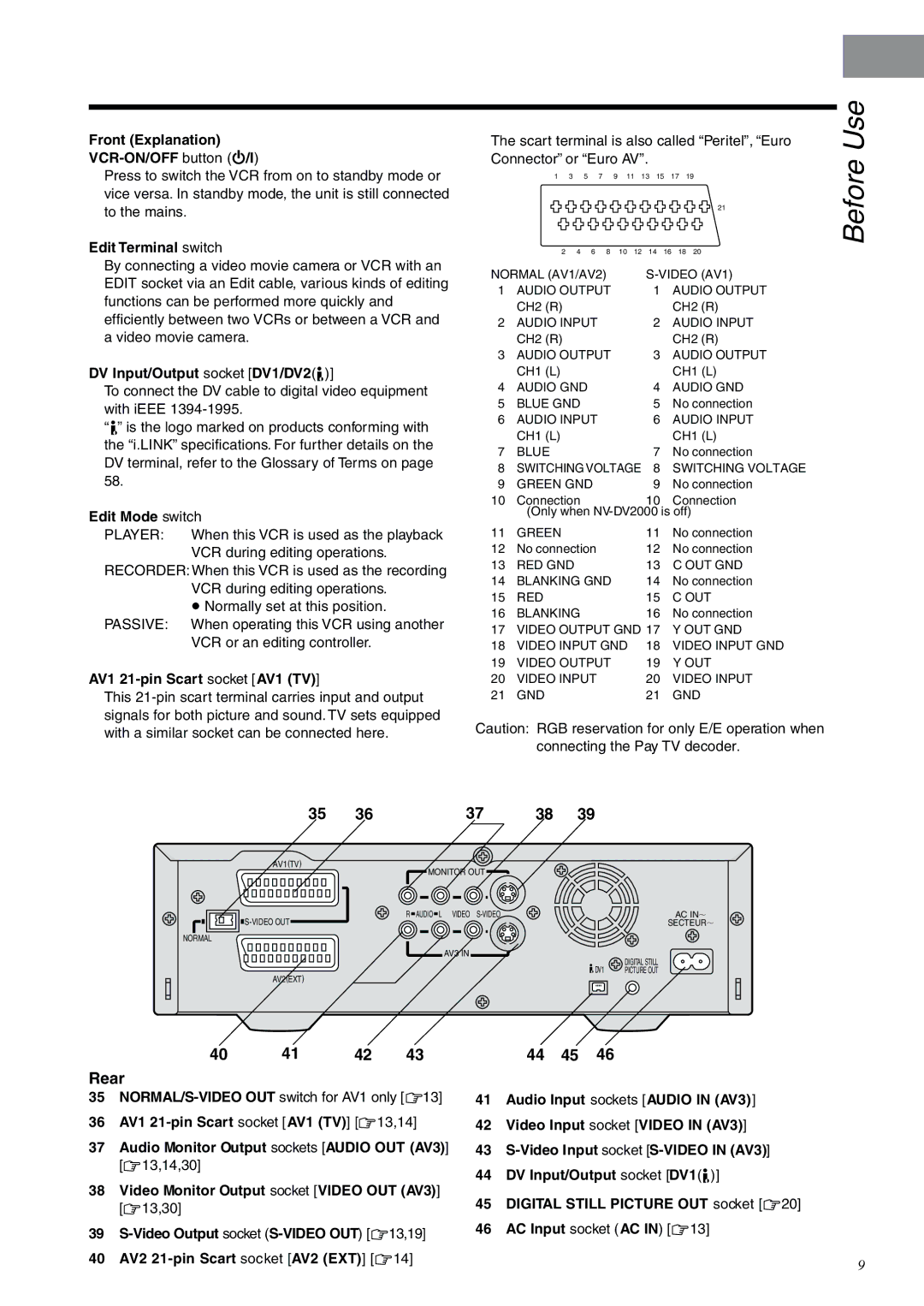
Rear
35
36AV1
37Audio Monitor Output sockets [AUDIO OUT (AV3)] [R13,14,30]
38Video Monitor Output socket [VIDEO OUT (AV3)] [R13,30]
39
40AV2
44 45 46
41Audio Input sockets [AUDIO IN (AV3)]
42Video Input socket [VIDEO IN (AV3)]
43
44DV Input/Output socket [DV1(¥)]
45DIGITAL STILL PICTURE OUT socket [R20]
46AC Input socket (AC IN) [R13]
9