GETTING STARTED
Step 3b. Digital TV Reception with
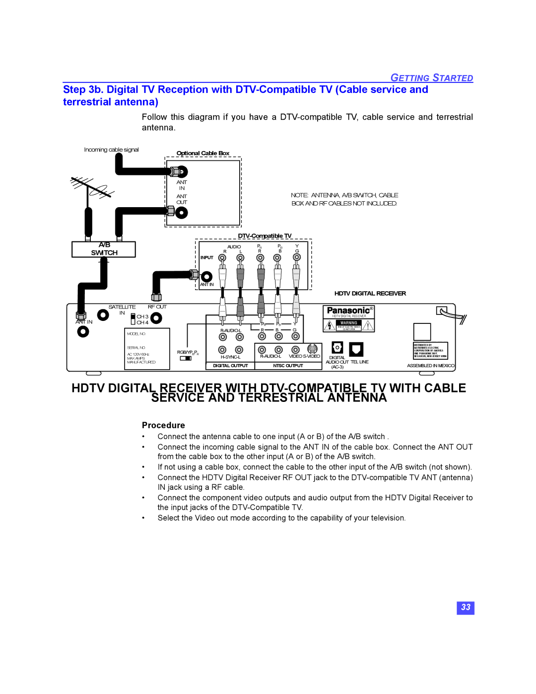
Follow this diagram if you have a
Incoming cable signal | Optional Cable Box |
|
ANT
IN
ANT OUT
NOTE: ANTENNA, A/B SWITCH, CABLE BOX AND RF CABLES NOT INCLUDED.
A/B
SWITCH
R | AUDIO | PR | PB | Y |
L | R | B | G |
INPUT
ANT IN
HDTV DIGITAL RECEIVER
SATELLITE | RF OUT | |
IN | CH 3 | |
ANT IN | ||
CH 4 | ||
MODEL NO. | ||
SERIAL NO. | ||
AC 120V 60Hz | ||
MAX AMPS | ||
MANUFACTURED | ||
|
| PR | PB | Y |
| R | B | G | |
RGB/YPBPR | VIDEO | |||
| ||||
| DIGITAL OUTPUT |
| NTSC OUTPUT | |
| ® |
HDTV DIGITAL RECEIVER |
|
WARNING | ! |
RISK OF ELECTRIC SHOCK | |
DO NOT OPEN |
|
|
|
|
|
|
| DISTRIBUTED BY |
|
|
|
|
|
|
|
| MATSUSHITA ELECTRIC |
|
|
|
|
|
|
|
|
| |
|
|
|
|
|
|
| CORPORATION OF AMERICA |
|
|
|
|
|
|
|
| ONE PANASONIC WAY, |
|
DIGITAL |
| SECAUCUS, NEW JERSEY 07094 |
| |||||
|
|
| ||||||
AUDIOOUT TEL LINE | ASSEMBLED IN MEXICO | |||||||
HDTV DIGITAL RECEIVER WITH
SERVICE AND TERRESTRIAL ANTENNA
Procedure
•Connect the antenna cable to one input (A or B) of the A/B switch .
•Connect the incoming cable signal to the ANT IN of the cable box. Connect the ANT OUT from the cable box to the other input (A or B) of the A/B switch.
•If not using a cable box, connect the cable to the other input of the A/B switch (not shown).
•Connect the HDTV Digital Receiver RF OUT jack to the
•Connect the component video outputs and audio output from the HDTV Digital Receiver to the input jacks of the
•Select the Video out mode according to the capability of your television.
33