INSTALLATION
Precautions
•The following steps of installation and connection work should be done by qualified service personnel or system installers and should conform to all local codes.
•Be sure to switch the camera off before installation and connection.
•Do not install the camera near the air outlet of an air conditioner.
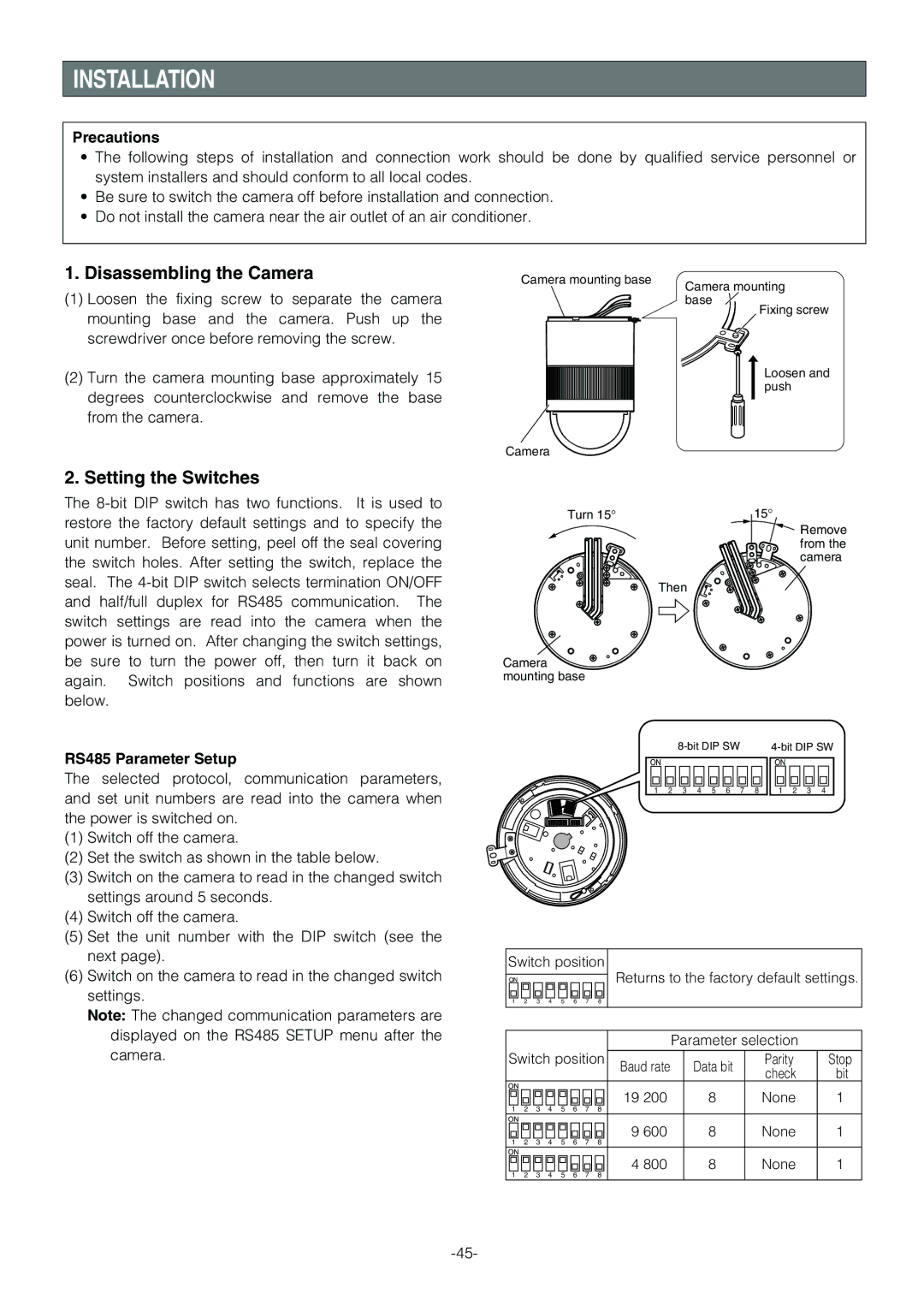
1. Disassembling the Camera | Camera mounting base | Camera mounting |
(1) Loosen the fixing screw to separate the camera |
| |
| base | |
mounting base and the camera. Push up the |
| Fixing screw |
|
| |
screwdriver once before removing the screw. |
|
|
(2)Turn the camera mounting base approximately 15 degrees counterclockwise and remove the base from the camera.
Loosen and push
Camera
2. Setting the Switches
The
RS485 Parameter Setup
The selected protocol, communication parameters, and set unit numbers are read into the camera when the power is switched on.
(1)Switch off the camera.
(2)Set the switch as shown in the table below.
(3)Switch on the camera to read in the changed switch settings around 5 seconds.
(4)Switch off the camera.
(5)Set the unit number with the DIP switch (see the next page).
(6)Switch on the camera to read in the changed switch settings.
Note: The changed communication parameters are displayed on the RS485 SETUP menu after the camera.
Turn 15° | 15° |
Remove from the camera
Then
Camera mounting base
|
|
|
| ||||||||
|
|
|
|
|
|
|
|
|
|
|
|
ON |
|
|
|
|
|
|
| ON |
|
|
|
1 | 2 | 3 | 4 | 5 | 6 | 7 | 8 | 1 | 2 | 3 | 4 |
Switch position | Returns to the factory default settings. | |||||||||||
|
|
|
|
|
|
|
| |||||
ON |
|
|
|
|
|
|
| |||||
1 | 2 | 3 | 4 | 5 | 6 | 7 | 8 |
|
|
|
|
|
|
|
|
|
|
|
|
|
|
|
|
|
|
|
|
|
|
|
|
|
|
|
|
|
|
|
|
|
|
|
|
|
|
|
| Parameter selection |
| ||
Switch position |
|
|
|
|
| |||||||
Baud rate |
| Data bit | Parity | Stop | ||||||||
|
|
|
|
|
|
|
|
| check | bit | ||
|
|
|
|
|
|
|
|
|
|
| ||
ON |
|
|
|
|
|
|
| 19 200 |
| 8 | None | 1 |
1 | 2 | 3 | 4 | 5 | 6 | 7 | 8 |
| ||||
|
|
|
|
| ||||||||
ON |
|
|
|
|
|
|
| 9 600 |
| 8 | None | 1 |
1 | 2 | 3 | 4 | 5 | 6 | 7 | 8 |
| ||||
|
|
|
|
| ||||||||
ON |
|
|
|
|
|
|
| 4 800 |
| 8 | None | 1 |
1 | 2 | 3 | 4 | 5 | 6 | 7 | 8 |
| ||||
|
|
|
|
| ||||||||