SmartNode 4400 Series Getting Started Guide | 3 • Hardware installation |
|
|
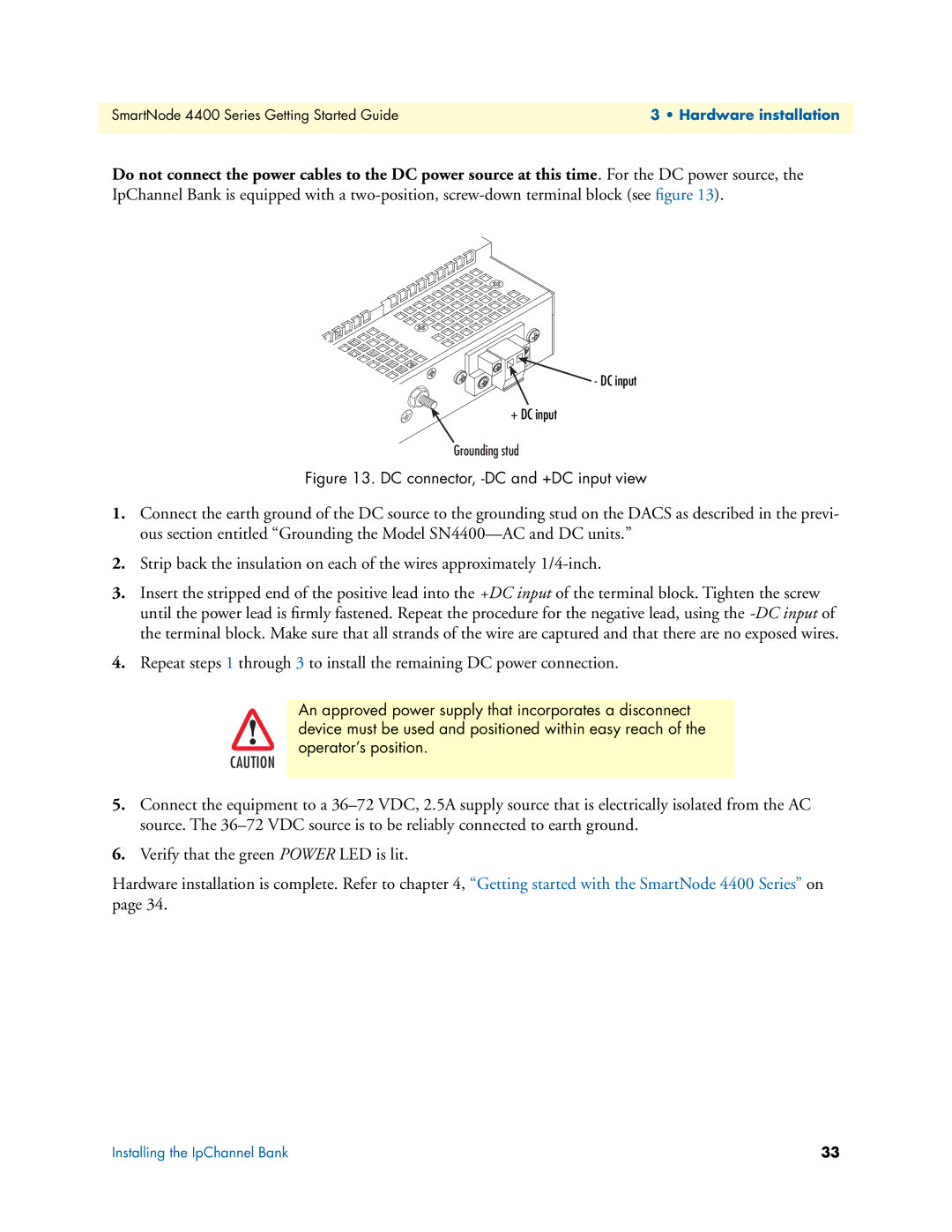
Do not connect the power cables to the DC power source at this time. For the DC power source, the IpChannel Bank is equipped with a
- DC input
+ DC input
Grounding stud
Figure 13. DC connector, -DC and +DC input view
1.Connect the earth ground of the DC source to the grounding stud on the DACS as described in the previ- ous section entitled “Grounding the Model
2.Strip back the insulation on each of the wires approximately
3.Insert the stripped end of the positive lead into the +DC input of the terminal block. Tighten the screw until the power lead is firmly fastened. Repeat the procedure for the negative lead, using the
4.Repeat steps 1 through 3 to install the remaining DC power connection.
An approved power supply that incorporates a disconnect device must be used and positioned within easy reach of the operator’s position.
CAUTION
5.Connect the equipment to a
6.Verify that the green POWER LED is lit.
Hardware installation is complete. Refer to chapter 4, “Getting started with the SmartNode 4400 Series” on page 34.
Installing the IpChannel Bank | 33 |