SmartNode 4400 Series Getting Started Guide | 3 • Hardware installation |
|
|
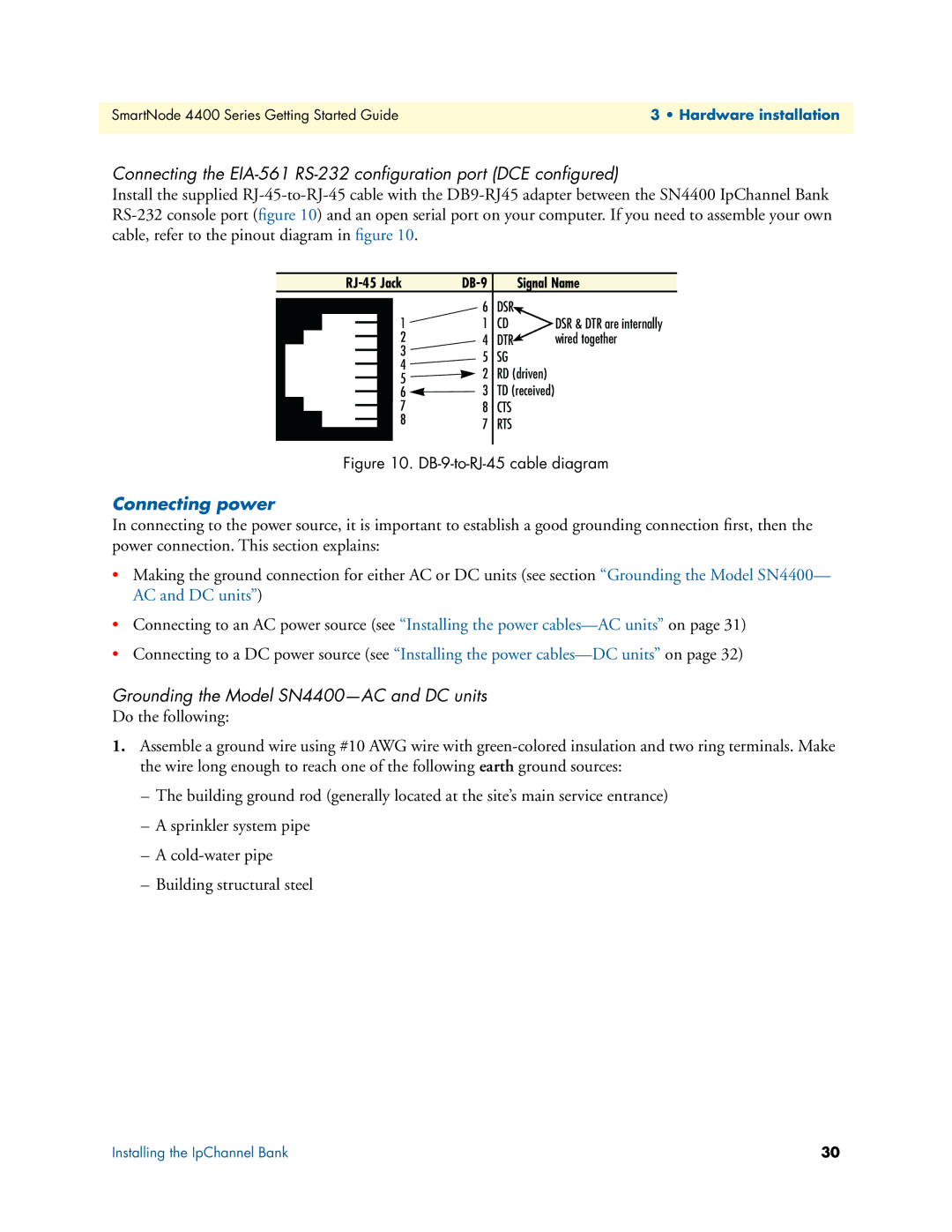
Connecting the
Install the supplied
Signal Name | |||||
|
|
| 6 | DSR |
|
|
| 1 | 1 | CD | DSR & DTR are internally |
| |||||
|
| 2 | 4 | DTR | wired together |
| |||||
|
| 3 | 5 | SG |
|
|
| ||||
|
| 4 |
| ||
|
| 2 | RD (driven) |
| |
|
| 5 |
| ||
|
| 3 | TD (received) |
| |
|
| 6 |
| ||
|
| ||||
|
| 7 | 8 | CTS |
|
|
| ||||
|
| 8 | 7 | RTS |
|
|
| ||||
|
|
|
| ||
|
|
|
|
|
|
Figure 10. DB-9-to-RJ-45 cable diagram
Connecting power
In connecting to the power source, it is important to establish a good grounding connection first, then the power connection. This section explains:
•Making the ground connection for either AC or DC units (see section “Grounding the Model SN4400— AC and DC units”)
•Connecting to an AC power source (see “Installing the power
•Connecting to a DC power source (see “Installing the power
Grounding the Model SN4400—AC and DC units
Do the following:
1.Assemble a ground wire using #10 AWG wire with
–The building ground rod (generally located at the site’s main service entrance)
–A sprinkler system pipe
–A
–Building structural steel
Installing the IpChannel Bank | 30 |