Eight HS and RT mixing consoles
HS block diagram
Table of contents
RT block diagram
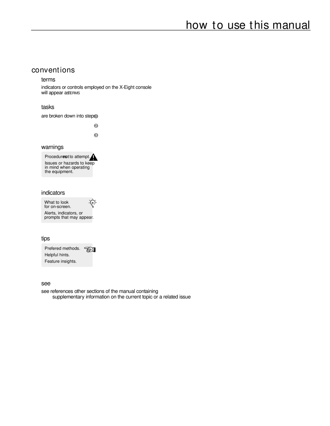
Conventions
Module Block diagram Panel
Phantom power-+48V
Features
Pad
Line
Mono input module
High-pass filter-HPF
Gain
Module
EQ features
Panel
Aux sends
Aux send features
Aux 1-4, 5/6 and 7/8 pre-fader-PRE
Aux stereo 5/6 and 7/8
Mono input module
Left-center-right-LCR
Bus assignment features
Pan control
Safe preview-LED
Mono input module
Write-in label
Mute
Mono input module
Peak indicator-PK
Level meter features
Signal level LED’s
Signal present indicator-SIG
Mono input module
Left / right assignment-L-R
Mono assignment-M
Group 1-8 assignment
Solo
Module Block diagram
Rear panel features
Stereo input module
Line select-Line
Left and right mono-switches
Stereo input module
Input gain-GAIN
Module
Equalizer-EQ on
Four-band stereo EQ features
Stereo input module
Stereo balance 7 and 8-STEREO
Aux send 1-8 controls
Stereo balance 5 and 6-STEREO
Stereo input module
Safe preview LED
Balance control
Stereo input module
Left/right assignment-L/R
Stereo input module
Balance on-groups-BAL on
Line
Line-input left and right 1/4TRS jacks
Balanced left and right line-in XLR connectors
Line-input left and right RCA connectors
Diagram
Mid frequency-MID
Output eq features
Module
Group equalization -per output channel-EQ to Group
Module
Post-group
Matrix features
Matrix 1-4 levels-M1, M2, M3, M4
Module
Aux 1-8 output level
Aux master output features
Module
Reverse aux / group
Reverse aux /group
Module
Mono assignment-fromgroup-MONO
Group assignment features
Left/right assignment-fromgroup-L/R
Pan
3group HS module
Fader
Group/aux level features
Signal/peak LED’s
Group Out Panel 3group HS module
Group insert point
Group output
Group insert send
Group insert return
3group HS
Lamp dim / meterbridge connectors
Auxiliary 1-8 output XLR’s
Meterbridge connector
Aux insert point
Aux insert send
4group RT module
Group output level control
Group output control features
Talk to
Post-fader
Module Block diagram
Post-fader-recessed
Matrix 1-4 level controls
4group RT module
Mono assignment
External tape input assignment features
Level
4group RT module
Aux pre-fader 5/6 and 7/8-PRE
Aux/group assignment features
Group-to-aux assignment-GROUP to AUX
4group RT module
Left/right assignment-L-R
Signal/peak LED-SIG/PEAK
Group mute
Group fader
Tape E r t
Insert point
Tape/line-input jack
Lamp dim/meterbridge connector detail
MIDI/DC power detail
Midi in, midi out
DC power-in
Matrix
Master HS module
High frequency-HF
Module Block diagram
Left,right,mono equalization-EQ to LEFT,TO RIGHT,TO Mono
Master HS module
Post-left, post-right, post-mono
Left, right, and mono levels-MATRIX1-4
External input levels-MATRIX1-4
External matrix routing-MTX 1 in to ALL
Master HS module
Matrix 1-4 talkback-TALK to
Matrix output features
Master output levels-MTX1-4
Master HS module
Pre switch
Alternate out features
Alternate out level
Sum mono
Master HS module
Sum left/right-SUM L/R
Talkback alternate-TALK to ALT OUT
Talkback left/right-TALK to L/R
Module
Left and right master faders
Left and right level features
Module Block diagram
Solo-off
Monitor output features
Monitor-out level
Master HS module
Main left/right to mono-L/R to Mono
Local monitor output features
Talkback mono-TALK to Mono
Module
Mono master fader
Mono master level features
Master HS module
Talkback level
Talkback features
Pink noise
Talkback on-TALK on
Module Block digram
Headphone level
Solo control features
Solo clear
Last pressed
Matrix
XLR output jack on monitor
Left and right alternate output XLR’s
Matrix 1-8 output XLR’s
Left, right and mono output XLR’s
Module Block diagram MIDI/DC power detail Panel
Insert points-left, right, and mono
Master RT module
Matrix talkback-TALK to
Matrix master output features
Matrix output levels-MTX1-4
Master RT module
MTX 1-to-all
Matrix level control features
External matrix 1-4 input levels controls
6master RT module
Auxilary 1-4 talkback-TALK to
Aux 1-8output levels
Module
Pre
Alternate output features
Alternate output level-ALT OUT
AUX BAL OUT
Signal /peak LED-SIG/PEAK
Left/right master fader features
Module
Solo off
Panel
Features
Panel
Left/right to mono-L/R to Mono
Mono talkback-TALK to Mono
Sig/peak LED-SIG/PEAK
Folo
Master RT module
Talk On
Master RT module
See-solo clear
Matrix Out Aux
Left, right, and mono insert points
Matrix 1-4output XLR’s
Monitor, alt, asst outputs and insert detail
Left and right monitor output XLR’s
Left, right, and mono output XLR’s
Hearing assist output
Block diagram Mute control panel Typical channel
Mute controller
Block diagram Mute control panel
Single Scene
Microprocessor muting system
Channel mute controls
Microprocessor muting system
Creating a mute scene-or editing an existing one
Mute scenes
Microprocessor muting system
Hold down the Micro Scene button.The display will show CPY?
Copying a mute scene
Microprocessor muting system
Clearing the Safe Scene
Safe scene
Microprocessor muting system
Utilities
Display Meaning Settings
Microprocessor muting system
Utility mode
Changing/reviewing utility settings
RT group rear-panel
Model 5A power supply
Specifications
Power requirements
Power supply usage
Supply identification
Ground linking
Power supply
Multiple power supplies in-series
Console and power supply grounding
Redundant power supplies
D7000009 12 /21 /99

