NOTE: Remember that the first few
|
|
|
|
| VGA MONITOR |
|
|
|
|
|
|
|
|
| |||
|
|
|
|
|
|
|
|
|
|
|
|
|
|
|
|
|
|
|
|
|
|
|
|
|
|
|
PIN 1
PRINTER | COM 1 | COM 2 |
PIN 8
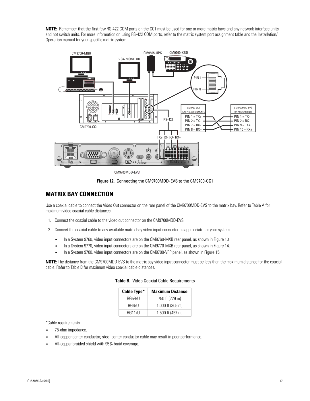
RJ45 PIN ASSIGNMENTS
PIN 1 = TX+
PIN 2 = TX-
PIN 7 = RX-
PIN 8 = RX+
PIN ASSIGNMENTS
PIN 1 = TX- PIN 2 = RX- PIN 9 = TX+ PIN 10 = RX+
TX+ TX- RX- RX+
Figure 12. Connecting the CM9700MDD-EVS to the CM9700-CC1
MATRIX BAY CONNECTION
Use a coaxial cable to connect the Video Out connector on the rear panel of the
1.Connect the coaxial cable to the video out connector on the
2.Connect the coaxial cable to any available matrix bay video input connector as appropriate for your system:
•In a System 9760, video input connectors are on the
•In a System 9770, video input connectors are on the
•In a System 9780, video input connectors are on the
NOTE: The distance from the
Table B. Video Coaxial Cable Requirements
Cable Type* | Maximum Distance |
|
|
RG59/U | 750 ft (229 m) |
|
|
RG6/U | 1,000 ft (305 m) |
|
|
RG11/U | 1,500 ft (457 m) |
|
|
*Cable requirements:
•
•
•
17 |