EtherLink III ISA Network Interface Card User Guide
3Com Corporation 5400 Bayfront Plaza Santa Clara, California
Lifetime Limited Warranty
Sweden, Finland, Norway
Contents
Running the AutoLink Install Program
To Configure Dynamic Access Software
To Not Save Installation Settings
To Obtain an IP Address Automatically
Installing from a Diskette
NIC Test Network Test Uninstalling the NIC
Performing Automated Installations
Checklist
Disable Receive Packet Buffering
Troubleshooting Hubs with Crossover Cable C-1
Low-Priority Ratio Natural Packet Interval
Update Device Driver Wizard Screen
Select Device Screen
DNS Configuration Screen
Save Installation Settings Screen
Tables
Option Settings
Diagnostic Programs
Parameters for 3C509B NIC Models
Page
How to Use This Guide
About this Guide
If you are looking for Turn to
Icon Alerts you to
Conventions
List conventions that are used throughout this guide
Convention Description
Network Interface Card Installation
Network Interface Card Overview
3Com 3C509B EtherDisk diskettes 1
NIC Model Cable Connector Transceiver Network Segment
Before You Begin
Maximum
Installing the NIC
2Installing the 3C509B NIC
Connecting to the Network
Go to Link LED later in this chapter
4Connecting to the BNC Port on the 3C509B-TPC NIC
Go to the next section
If the NIC LED indicates a problem, check the following
Link LED
Describes the LED states
Page
Setup for Custom Installation
Selecting the Type of Installation
Express Installation
Future installations
Windows 95 Setup
Custom Installation
Multiple NIC Installations
Windows 95 Setup
3Com Installation Wizard
Performing the Preinstallation Procedure
Follow these steps to perform the preinstallation procedure
Click OK
Turn the power on and boot Windows
Configuring the NIC in a Plug and Play PC
3Com Installation Wizard starts. Go to Chapter
Insert EtherDisk diskette 1 in drive a Click Next
Click Finish
DOS Pnpdsabl screen appears, as shown in Figure
Plug and Play is disabled on the NIC
Disabling Plug and Play on the NIC
Next step is to configure the NIC
Configuring the NIC
Add New Hardware Wizard starts and displays the first screen
Select No, and then click Next
8Install from Disk Screen
Windows NT Setup
10I/O Range Assigned to the NIC Screen
Windows NT Setup
Network screen appears
Select OEM Option screen appears
Custom Installation
Follow these steps to perform a Custom installation
To Accept Configuration Settings
Configuring the NIC
Testing the NIC and the Network Connection
To Modify Configuration Settings
Network Connection Test screen appears, as shown in Figure
Follow these steps to test the NIC
Message confirms that the NIC is functioning correctly
Follow these steps to test the network connection
To Install TCP/IP
Installing TCP/IP Under Windows
To Not Install TCP/IP
Select the No radio button Click Next
Follow these steps to obtain an IP address automatically
Configuring TCP/IP Under Windows
To Obtain an IP Address Automatically
Go to Configuring DNS later in this chapter
To Specify an IP Address Manually
Click Add New Gateway to add the new gateway configuration
Follow these steps to obtain a DNS address automatically
Configuring DNS
To Obtain a DNS Address Automatically
Message confirms that the DNS connection is functioning
New server appears in the Servers list box
To Specify a DNS Address Manually
Follow these steps to specify a DNS address manually
Next step is to identify your PC on the network
Follow these steps to enter field data
Next step is to configure DynamicAccess software
Identifying Your PC on the Network
Type the name of your computer
Configuring DynamicAccess Software
To Not Configure DynamicAccess Software
To Configure DynamicAccess Software
Pace Support Setup screen appears, as shown in Figure
Double-click the 3Com Pace Config icon shown in Figure
Repeating a Previous Installation
To Not Save Installation Settings
To Save Installation Settings
Select the Yes radio button, and then click Next
Installation Complete screen appears, as shown in Figure
Click Finish
Completing the Installation and Configuration
Windows
Click Yes
Windows NT
Click Close
Choose a method to configure TCP/IP
19Microsoft TCP/IP Properties Screen
Select the Specify an IP address radio button
Page
Under Windows
Configuration
Running the AutoLink Install Program
AutoLink Requirements
AutoLink program menu is displayed
I N N U
NetWare Server NLM Name
Installing Other Supported Network Drivers
Obtaining NetWare Loadable Modules
Network Text File Name Network Driver Name Operating System
Select Configure NIC and press Enter
Removing NIC Software
NIC software is removed from your PC
NIC Configuration screen is displayed, as shown in Figure
Reconfiguring the NIC
Select Auto Configure and press Enter
Changing NIC Configuration from ISA to Eisa
Follow these steps to configure the 3C509B ISA NIC for an
Changing NIC Configuration from Eisa to ISA
Changing Configuration Settings
Option Default Setting Supported Settings
Follow these steps to change the configuration settings
Page
Windows 95 Windows NT Troubleshooting
Checklist
Resolving Hardware Conflicts in Windows 95 and Windows NT
System Properties window is displayed
Close all open windows and restart the PC
General tab of the 3Com NIC Diagnostics program appears
Double-click the 3Com icon in the taskbar tray
Restart the PC
Setup program copies files, and the Network screen reappears
Installing Multiple NICs in a Windows NT PC
Installing the First NIC
3Com EtherLink III 3C509 ISA Adapter Bus screen appears
Microsoft TCP/IP Properties screen appears
Installing Subsequent NICs
Setup program displays a warning message
Files are copied, and the Network screen reappears
Starting the 3Com NIC Diagnostics Program
Windows 95 and Windows NT Troubleshooting
Diagnostic Testing Under Windows 95 and Windows NT
Messages are displayed, and you are prompted to reboot
Tab Description General
Diagnostics
DynamicAccess
Configuration
Uninstalling the NIC
Running Tests
Reinstalling NIC Software
Click Remove Click OK
Installing from a Diskette
Performing Automated Installations
Installing from the Hard Disk
Click Install
Windows Troubleshooting
Diagnostic Testing Under Windows
Running the Group 1 Tests
Starting the DOS Configuration and Diagnostic Program
If multiple NICs are installed, each NIC is listed
Select the NIC you want to test and press Enter
Follow these steps to run the Group 1 tests
Failure in this test usually indicates a cabling problem
Running the Group 2 Test
Assembling a Loopback Plug
Running the Group 3 Test
Setting Up an Echo Server
Follow these steps to set up an echo server
Starting the Group 2 Test
Main window of the diagnostic program is displayed
Diagnostic NIC Installed Program Name Echo Server
Starting the Group 3 Test
Getting Help If a Test Fails
Specifications
NIC Specifications
RJ-45 Connector Pin Assignments
AUI Connector Pin Assignments
Pin Function
Cable Specifications
TypeExample
Page
Additional Ranges Tab
Additional Ranges tab is shown in Figure B-1
Advanced Options Tab
Click Add
Low-Priority Ratio
Fifo Packet Threshold
Concurrent UDP Streams
Natural Packet Interval
Disable Switch Packet Prioritization
Disable Receive Packet Buffering
This option disables the receive packet buffer
Troubleshooting Hubs with Crossover Cable
Crossover Cable
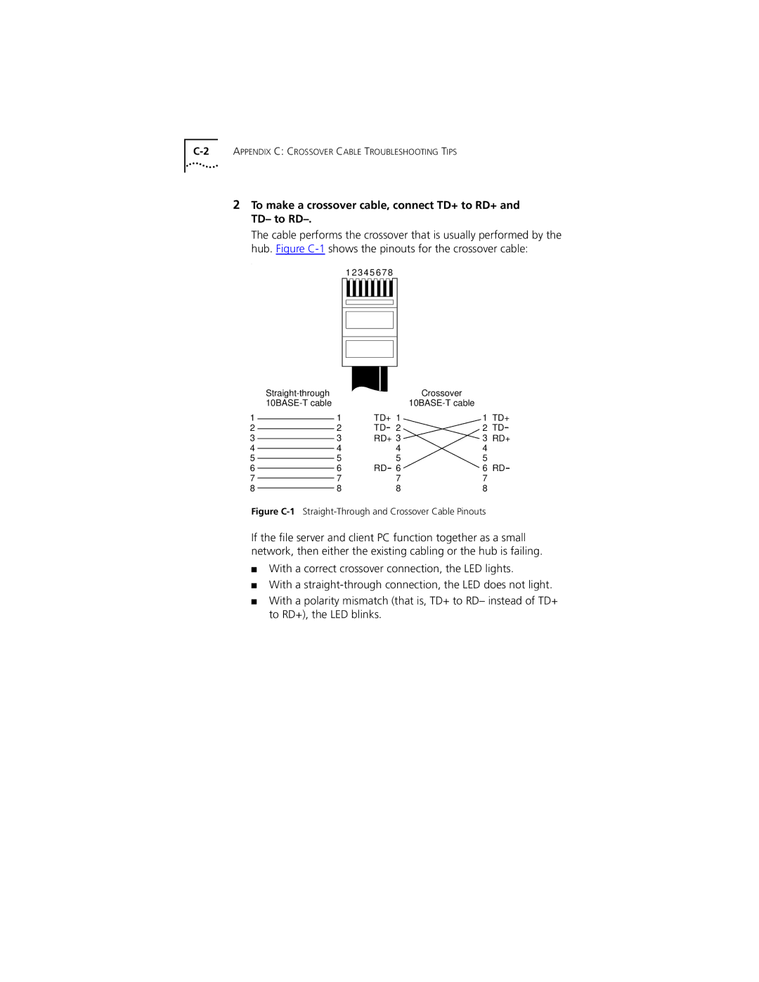
To make a crossover cable, connect TD+ to RD+ and TD- to RD
Figure C-1Straight-Through and Crossover Cable Pinouts
Online Technical Services
3Com Bulletin Board Service
World Wide Web Site
Access by Digital Modem
3ComFacts Automated Fax Service
Access by Analog Modem
408 654
To use 3ComForum
3ComForum on CompuServe Online Service
Support from Your Network Supplier
Log on to CompuServe
Support from 3Com
Regional Sales Office Telephone Number 3Com Corporation
3Com Ireland
Returning Products for Repair
To obtain an RMA number, call or fax
Country Telephone Number Fax Number
Index
Numbers
Index
NIC
Page
3Com Corporation Limited Warranty
FCC Class B Statement
FCC Declaration of Conformity
Page
Page
Page
Page
Page