NOTE: The instructions given here are for templates mounted to the base of the jig. However, this joint can also be made with templates mounted to angled clamping boards. You must use the angled clamping board for steeper angles.
Use the following table for setting up your table saw for these cuts:
|
|
|
|
|
DESIRED SIDE ANGLE |
| MITER gauge ANGLE |
| BLADE TILT ANGLE |
|
|
|
|
|
85° |
| 85.0° |
| 89.6° |
|
|
|
|
|
80° |
| 80.1° |
| 88.3° |
|
|
|
|
|
75° |
| 75.5° |
| 86.2° |
|
|
|
|
|
70° |
| 71.1° |
| 83.3° |
|
|
|
|
|
65° |
| 67.1° |
| 79.7° |
|
|
|
|
|
|
|
|
|
|
SETUP
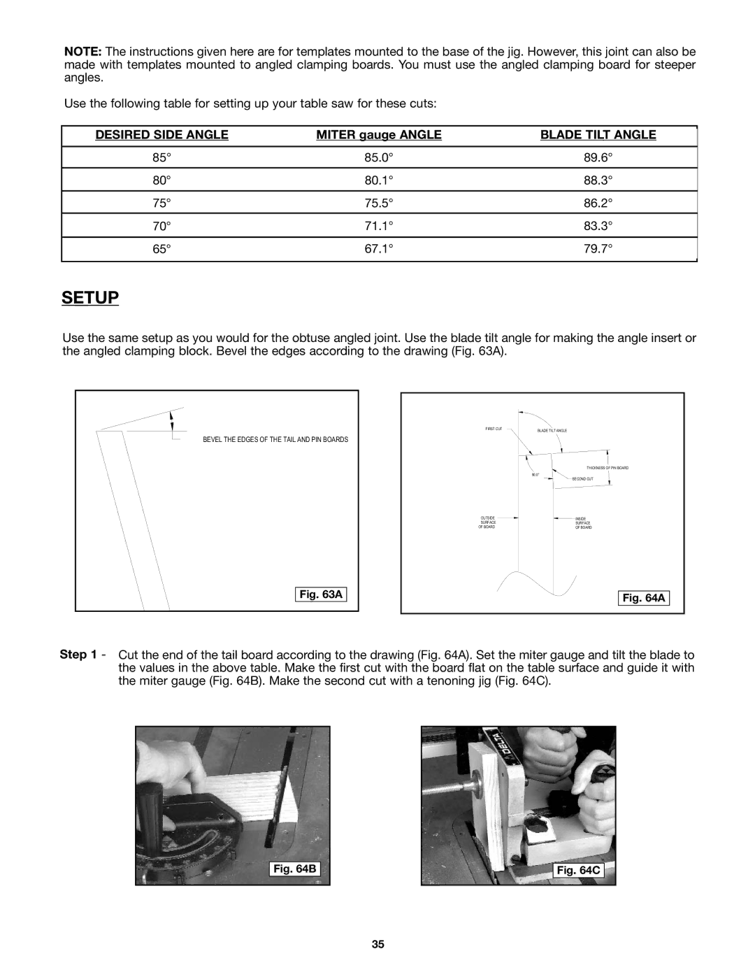
Use the same setup as you would for the obtuse angled joint. Use the blade tilt angle for making the angle insert or the angled clamping block. Bevel the edges according to the drawing (Fig. 63A).
BEVEL THE EDGES OF THE TAIL AND PIN BOARDS
Fig. 63A
FIRST CUT | BLADE TILT ANGLE |
|
THICKNESS OF PIN BOARD
| 90.0° |
| SECOND CUT |
OUTSIDE | INSIDE |
SURFACE | SURFACE |
OF BOARD | OF BOARD |
Fig. 64A
Step 1 - Cut the end of the tail board according to the drawing (Fig. 64A). Set the miter gauge and tilt the blade to the values in the above table. Make the first cut with the board flat on the table surface and guide it with the miter gauge (Fig. 64B). Make the second cut with a tenoning jig (Fig. 64C).
Fig. 64B
Fig. 64C
35