Step 4 - Slide the straight clamping block to the left so that it contacts the pin board (Fig. 16D). Hook the straight clamping block over the front and back of the main clamping board.
Step 5 - Secure the pin board by clamping it between the offset and straight clamping blocks (Fig. 16E).
Step 6 - Loosen the #10 wood screws, align the template lines with the line where the pin board and tail board meet, and retighten the #10 wood screws (Fig. 16F).
DISCONNECT THE TOOL FROM THE POWER SOURCE.
Step 7 - Set the router bit depth, using the bit depth guide.
Step 8 - Cut the joint. Fitting the joint is identical to a standard
NOTE: You can cut the pin and tail board separately, if you prefer.
Fig. 16D
Fig. 16E
Fig. 16F
USING A ROUTER TABLE
You can use
Fig. 17A
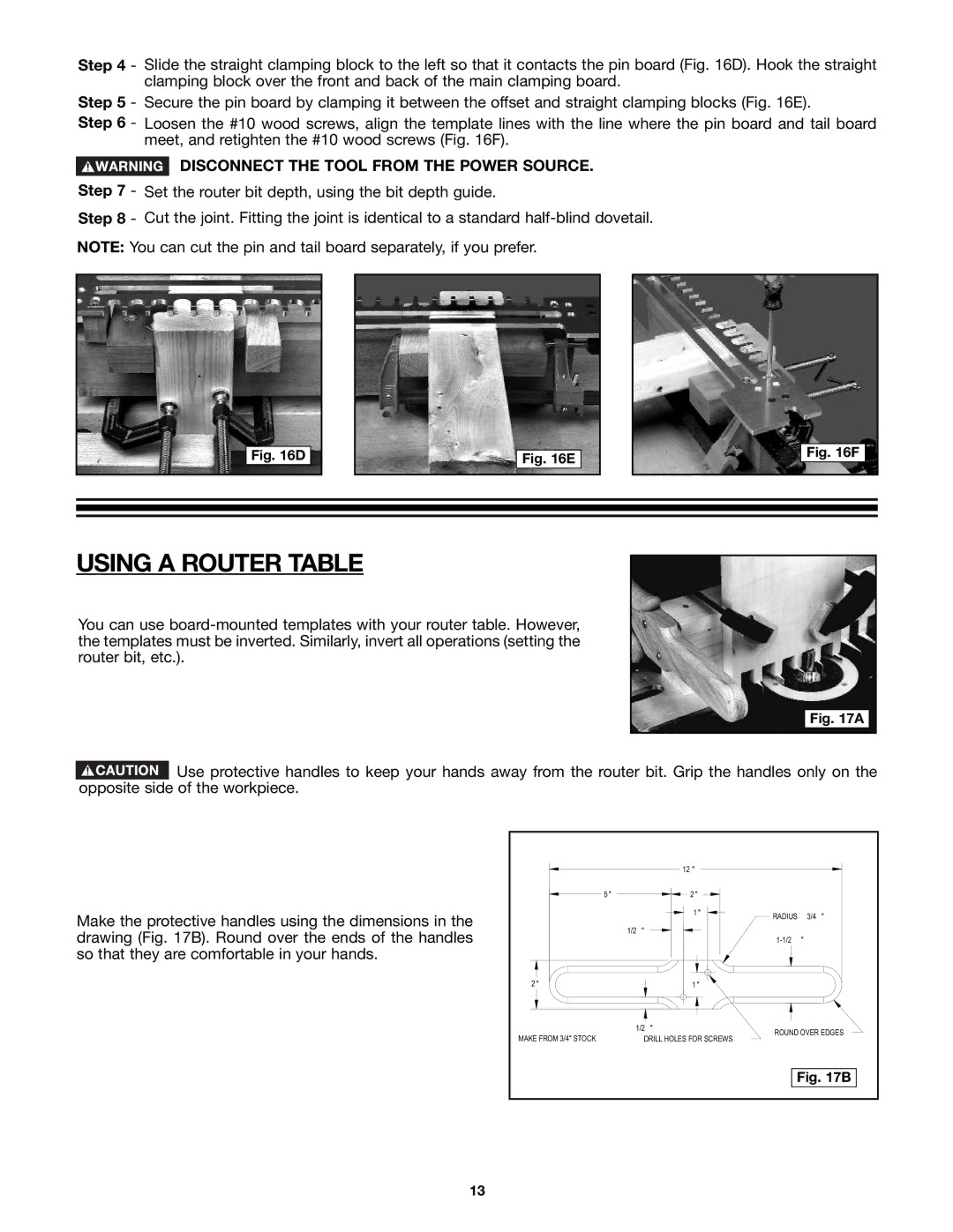
![]() Use protective handles to keep your hands away from the router bit. Grip the handles only on the opposite side of the workpiece.
Use protective handles to keep your hands away from the router bit. Grip the handles only on the opposite side of the workpiece.
Make the protective handles using the dimensions in the drawing (Fig. 17B). Round over the ends of the handles so that they are comfortable in your hands.
|
| 12 " |
|
| |
5 " |
| 2 " |
|
| |
|
| 1 " | RADIUS | 3/4 " | |
|
|
| |||
1/2 | " |
|
|
| |
|
|
| " | ||
2 " |
| 1 " |
|
| |
1/2 | " | ROUND OVER EDGES | |||
MAKE FROM 3/4" STOCK | DRILL HOLES FOR SCREWS | ||||
|
| ||||
|
|
| Fig. 17B | ||
13