Communication |
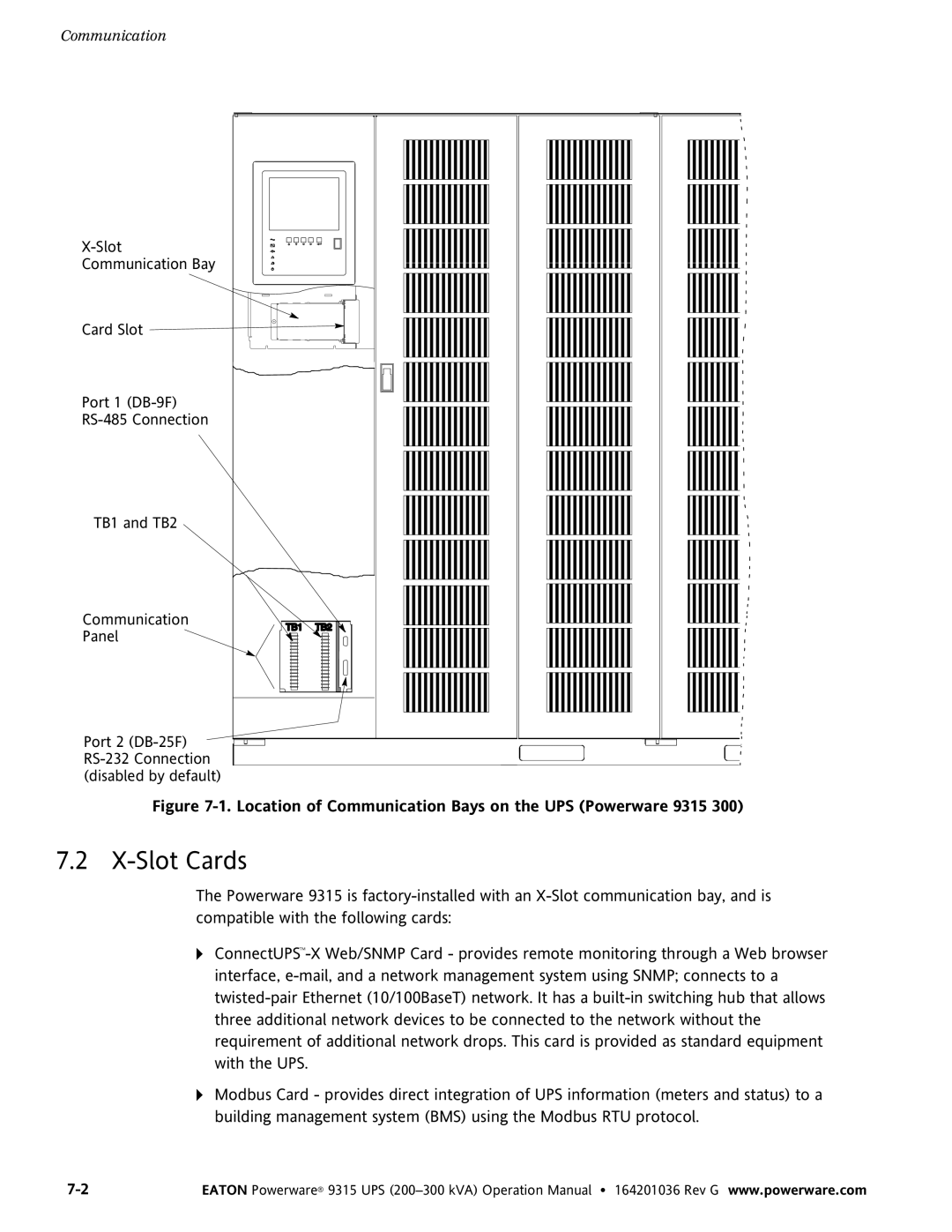
X−Slot |
Communication Bay |
Card Slot |
Port 1 (DB−9F) |
RS−485 Connection |
TB1 and TB2 |
Communication |
Panel |
Port 2 (DB−25F) |
RS−232 Connection |
(disabled by default) |
Figure 7-1. Location of Communication Bays on the UPS (Powerware 9315 300)
7.2 X−Slot Cards
The Powerware 9315 is factory−installed with an X−Slot communication bay, and is compatible with the following cards:
AConnectUPSt−X Web/SNMP Card − provides remote monitoring through a Web browser interface,
AModbus Card − provides direct integration of UPS information (meters and status) to a building management system (BMS) using the Modbus RTU protocol.
7−2 | EATON Powerware® 9315 UPS |