DLT7000 Tape System Product Manual
Service Centers
Achtung
Page
Page
Page
Table of Contents
Table of Contents
Overview of Command and Status Processing
Supported Pages Log Page Page 00h
Changeable Parameters within Mode Select 104
Mode Sense Mode Pages 112
Read Command 08h 133
Rewind Command 01h 165
Index-1
Figures
DLT 7000 Termpwr and Parity Check Jumper Locations
Mode Select Mode Parameter Header Data Format
Quantum DLT 7000 Tape System Xiii
Read Position Command Descriptor Block Data Format 143
Space Command Descriptor Block Data Format 173
144
Data Format 147
Tables
DATA-Phase Command Contents
Log Parameters for Device Status LOG Sense Page Field
107
109
111
113
170
171
178
Table B-2
Revision History
Revision History
General Description and Specifications
Audience
Purpose
Document Organization
Scsi Commands
Hardware Implementation
Scsi Description
Chapter Scsi Messages
Conventions
For More INFORMATION…
Appendix C Updating the Firmware
Appendix D The Tape Cartridge
Reader Comments
General Description and Specifications
Product Description
Product Features
Product Specifications
Physical Specifications
General Description and Specifications
Interface Type
Storage Capacity
Reliability Projected
DLT 7000 Storage Capacity
Performance Data
−3 DLT 7000 Performance Data
−4 DLT 7000 Environmental Specifications
Environmental Specifications
DLT 7000 Storage and Shipping Specifications
Quantum DLT 7000 Tape System
Quantum DLT 7000 Tape System
Power Requirements
DLT 7000 Power Requirements
Current Requirements
−9 DLT 7000 Current Requirements
Tape System Recording Type
Acoustic Noise Emissions
−10 Acoustic Noise Emissions, Nominal
−12 DLTtape Media Specifications
DLTtape Recording Media Specifications
−13 DLTtape Cartridge Operating and Storage Limits
Electromagnetic Emissions
Electromagnetic Interference EMI Susceptibility
Conducted Emissions
14 EMI Regulations and Certifications
Susceptibility
Radiated Emissions
Radiated Emissions
General Description and Specifications
SAFETY, Handling and Electrostatic Discharge ESD Protection
Hardware Implementation
Handling
Safety Precautions
Hardware Implementation
Configuring and Installing a Rackmount Tape Drive
Electrostatic Discharge ESD Protection
Setting the Rackmount Drive Scsi ID
Scsi ID
Configure The Rackmount Drive for Parity Checking
Configure the Rackmount Drive for Termpwr Single-Ended Only
Termpwr
Installing the Rackmount Tape Drive
Securing the Rackmount Tape Drive
Rackmount Drive Mounting Locations Side and Bottom Views
Connecting the Rackmount Drive Cables
Scsi and Power Connectors Rackmount
Signal Name Pin Number Ground
+ATN
+BSY
+ACK
+MSG
Optional Loader Connector Rackmount
Signal Name Pin Number
Configuring and Installing a Tabletop Drive
Configuring the Tabletop Drive
AC Power Cable
Installing the Tabletop Drive
Scsi Cables
115 220 / 240
Drive Controls and Light Emitting Diodes Leds
Front Panel Controls and LEDs
LED Functionality
LED
Hardware Implementation LED Functionality
Hardware Implementation Density LED Functionality
Density LED Description Amber
Hardware Implementation Control Functionality
Selecting Density
Selecting Density on the Tape Drive
For Example
LED Activity During Density Selection
Power on Self Test Post
Selecting Density via the Host over the Scsi Bus
Hardware Implementation 10 POST/Media Ready Activity
11 Tape Drive States Following Initialization
Troubleshooting
12 Troubleshooting Chart
Hardware Implementation 12 Troubleshooting Chart
Scsi Description
Scsi Overview
Implemented Ansi SCSI-2 Commands
Scsi Commands
Scsi Description
Implemented Ansi SCSI-2 Command
Signal Values
Signal States
Scsi Description Implemented Ansi SCSI-2 Command
Command
Signal Sources
Scsi ID Bits
Scsi Signal Definitions
Scsi Signals
SCSI-2 Bus Signal Definitions
Scsi Description SCSI-2 Bus Signal Definitions
Signal Bus Timing
Scsi Bus Timing Values
Scsi Description Scsi Bus Timing Values
Arbitration
Scsi Description
Scsi BUS Phases
BUS Free Phase
∙ Disconnect ∙ Command Complete
Arbitration Phase
Selection Phase
Selection Sequence
Selection Time-Out
Reselection Phase
Reselection Sequence
Reselection Time-Out
Information Transfer Phases
DLT 7000 supports block size of 1 byte to 16 Mbytes
Information Transfer Direction
Scsi Description Information Transfer Phases
Asynchronous Data Transfer
Synchronous Data Transfer
Signal Restrictions Between Phases
Status Phase
Status Bytes
Scsi BUS Conditions
Reset Condition
Drive Message OUT Phase Response
SELECTION1
RESELECTION2
Queued Unit Attentions
Messages
Message Format
Messages Message Format
Messages Supported Messages
Messages
Modify Data Pointer
BUS Device Reset Message 0Ch
Command Complete Message 00h
Supported Scsi Messages
Abort Message 06h
Disconnect Message 04h
Drive Response to Disconnect Message
Selection
Complete
Identify Message 80h FFh
Identify Message Field Description
Luntran
Luntar
Ignore Wide Residue Message 23h
Initiator Detected Error Message 05h
Drive Response to Initiator Detected Error Message
Linked Command Complete Message 0Ah
Linked Command COMPLETE, with Flag Message 0Ah
Message Parity Error Message 09h
Message Reject Message 07h
Restore Pointers Message 03h
No Operation 08h
Save Data Pointer Message 02h
Synchronous Data Transfer Request Message 01h
Synchronous Data Transfer Request Message Data Format
Wide Data Transfer Request Message 01h
Wide Data Transfer Request Message Data Format
Messages
Overview of Command and Status Processing
Supported Scsi Commands
Receive Diagnostic Results
Prevent Allow Medium Removal
Scsi Commands Supported Scsi Commands
Rewind
Scsi Commands
Scsi Pointers
MSB
Command Descriptor Block
LBA LSB
Scsi Commands Command Descriptor Block Field Descriptions
Field Description Operation Code
Status/Error Reporting
Status Codes
DATA-Phase Command Components
DATA-Phase Command Contents
Scsi Commands DATA-Phase Command Contents
Unit Attention Condition
Behavior at Power-On and Scsi Bus Reset
Data Cache and Tape Write Interaction
Scsi Command Descriptions
Bit Byte Bytes 0
Erase Command 19h
Inquiry Command Descriptor Block Data Format
Inquiry Command 12h
Evpd
Inquiry Command 12h
Inquiry Command Descriptor Block Field Descriptions
Standard Inquiry Data
Vital Product Data Page Codes
Standard Inquiry Data Page Data Format
RMB
Standard Inquiry Data Page Field Descriptions
Aenc
Vendor Unique Inquiry Data
Inquiry Vendor Unique Bytes Definitions
10 Vendor Unique Inquiry Data Page Field Descriptions
Supported Vital Product Data
Supported Vital Product Data Pages Page Data Format
Bit Byte Peripheral Qualifier
Peripheral Qualifier
10 Subsystem Components Revision Page C1h Data Format
13 Subsystem Components Revision Page Field Descriptions
Load Unload Command 1Bh
Load Unload Command 1Bh
11 Load Unload Command Descriptor Block Data Format
14 Load Unload Command Descriptor Block Field Descriptions
EOT
Locate Command 2Bh
12 Locate Command Descriptor Block Data Format
Locate Command 2Bh
15 Locate Command Descriptor Block Field Descriptions
LOG Select Command 4Ch
13 LOG Select Command Descriptor Block Data Format
LOG Select Command 4Ch
16 LOG Select Command Descriptor Block Field Descriptions
PCR
Field in CDB
Log Detection Summary in LOG Select Command Descriptor Block
Operation of LOG Select
Log Select Page Format
Parameter Code
ETC
TSD
TMC
Error Detection Summary in LOG Select Pages
LOG Sense Command 4Dh
16 LOG Sense Command Descriptor Block Data Format
LOG Sense Command 4Dh
19 LOG Sense Command Descriptor Block Field Descriptions
PPC
Invalid Field in CDB
Code Definition See Section
Illegal REQUEST, Invalid Field in CDB
Supported Pages Log Page Page 00h
17 Supported Pages Page Data Format
Read Page 03h / Write Page 02h Error LOG Sense
Field Name Description Parameter
Default is
Code Basis of Comparison
Last n Error Events Page 07h
LSB TSD ETC TMC
TapeAlert Page 2Eh
5n +
26 TapeAlert Flags, Severity Levels, and Meanings
Expired Cleaning
Read / Write Compression Page 32h
Target Save Disable. Not supported. This bit always set to
Parameter Code Descriptions
This page. Always set to
Bytes written to the tape drive
Device Wellness Page 33h
Media ID
List Parameter. Always set to
Device Status Page 3Eh
Code Description
Target-defined method has been disabled by the initiator
Mode Select 6 / 10 Command 15h / 55h
Mode Select 6 Command Descriptor Block Data Format
Mode Select 10 Command Descriptor Block Data Format
Mode Select 6 / 10 Command 15h / 55h
Mode Parameter List
36 Mode Select Mode Parameter List Field Descriptions
Mode Parameter Header
37 Mode Select Mode Parameter Header Field Descriptions
Mode Select 6 /10 Command 15h /55h
Mode Parameter Block Descriptor
Field Name Description Density
Mode Page Descriptors
36 Mode Select Page Descriptor Data Format
Read / Write Error Recovery Page 01h
39 Mode Select Page Descriptor Field Descriptions
40 Error Recovery Page Field Descriptions
Disconnect / Reconnect Page 02h
Dtdc
41 Disconnect / Reconnect Page Field Descriptions
For when disconnect is permitted
Control Mode Page 0Ah
Raenp
42 Control Mode Page Descriptor Field Descriptions
Rlec
Eeca
Uaaenp
Data Compression Page 0Fh
DCE
43 Data Compression Page Descriptor Field Descriptions
DCC
DDE
RED
Device Configuration Page 10h
Device Configuration Page Data Format
CAP
44 Device Configuration Page Field Descriptions
CAF
DBR
BIS
AVC
Socf
Medium Partition Page 11h
42 Medium Partition Page Format Descriptor Data Format
Medium Partition Page Descriptor Field Descriptions
FDP
SDP
IDP
TapeAlert Page 1Ch
Mrie MSB
46 TapeAlert Page Format Descriptor Field Descriptions
Mrie
Eeprom Vendor Unique Page 3Eh
44 Eeprom Vendor Unique Page Data Format
47 Eeprom Vendor Unique Page Parameters
Eeprom Vendor Unique Page Parameters
Hostcompsetting
Enbinqmedchgr
Forcecomp
Forcedensity
Loaderlun
Ldrcyclreset
Longxportpage
Maxburstsize
Nodeferrcvderr
Nodisconfxdblk
Nordyuaonunld
Rewindonreset
Scsibusdmatimer
Protectdironwp
Redundancymode
Scsireselretries
Scsiresrelnop
Seteomatbom
Seteomatew
Eeprom Vendor Unique Page Vendor ID Sample Data Format
Eeprom Vendor Unique Page Forced Density Example Data Format
Changeable Parameters within Mode Select
48 Changeable Mode Parameters within Mode Select
Mode Sense 6 / 10 Command 1Ah / 5Ah
47 Mode Sense 6 Command Descriptor Block Data Format
Mode Sense 6 / 10 Command 1Ah / 5Ah
48 Mode Sense 10 Command Descriptor Block Data Format
49 Mode Sense Control Descriptor Block Field Descriptions
DBD
Mode Sense Data Headers
49 Mode Sense 6 Data Header Data Format
50 Mode Sense Data Header Field Descriptions
Commands until the data blocks are actually written to tape
Mode Sense Block Descriptor
51 Mode Sense Block Descriptor Data Format
51 Mode Sense Block Descriptor Field Descriptions
Mode Sense Mode Pages
52 Mode Sense Page Descriptor Data Format
Sense
52 Mode Sense Page Descriptor Field Descriptions
Both
Read / Write Error Recovery Page 01h
53 Read / Write Error Recovery Page Data Format
53 Read / Write Error Recovery Page Field Descriptions
Select
Disconnect / Reconnect Page 02h
54 Disconnect / Reconnect Page Data Format
54 Disconnect / Reconnect Page Field Descriptions
Control Mode Data Format
55 Control Mode Page Field Descriptions
56 Data Compression Page Data Format
56 Data Compression Page Field Descriptions
118 Quantum DLT 7000 Tape System
57 Device Configuration Page Field Descriptions
120 Quantum DLT 7000 Tape System
58 Medium Partition Page Data Format
58 Medium Partition Page Field Descriptions
59 TapeAlert Page Format Descriptor Data Format
59 TapeAlert Page Format Descriptor Field Descriptions
Quantum DLT 7000 Tape System 125
Defaultcompon
Eeprom Vendor Unique Page 3Eh
Prevent / Allow Medium Removal Command 1Eh
Read Command 08h
Sili
Read Command 08h
61 Read Command Descriptor Block Field Descriptions
Read Command 08h
Read Block Limits Command 05h
62 Read Block Limits Command Descriptor Block Data Format
Read Block Limits Command 05h
62 Read Block Limits Data Field Descriptions
Read Buffer Command 3Ch
64 Read Buffer Command Descriptor Block Data Format
Read Buffer Command 3Ch
63 Read Buffer Command Descriptor Block Field Descriptions
Combined Header and Data Mode
Data Mode
Descriptor Mode
66 Read Buffer Descriptor Data Format
Read Position Command 34h
Read Position Command 34h
BOP
EOP
66 Read Position Data Field Descriptions
BPU
Receive Diagnostic Results Command 1Ch
Receive Diagnostic Results Command 1Ch
70 Receive Diagnostic Results Data Format
Release Unit Command 17h
Device ID
Release Unit Command 17h
Media Changer Considerations
Request Sense Command 03h
Request Sense Command 03h
73 Request Sense Data Format
70 Request Sense Data Field Descriptions
EOM
ILI
Ready
Sksv
BPV
71 Supported Sense Keys
Sense Code Qualifier bytes
72 Supported ASC / Ascq in Hex
Supported ASC / Ascq in Hex
Hardware Error
Ascq
ASC Ascq
Unit Attention
Data Protected
Blank Check
Vendor Unique
0Bh IDE Message Error
Reserve Unit Command 16h
Reserve Unit Command 16h
Rewind Command 01h
Send Diagnostic Command 1Dh
75 Send Diagnostic Command Data Field Descriptions
Send Diagnostic Command 1Dh
76 Send Diagnostic CDB Bits Selftst, DevOfl, and UnitOfl
77 Send Diagnostic Parameter List Data Format
77 Send Diagnostic Parameter List Field Descriptions
FF FF FF FF FF
FE FD FB F7 EF DF BF 7F
MFM DE AD DE AD DE AD DE AD AA AA AA AA AA AA AA AA
78 Sense Keys Used for Send Diagnostic
79 ASC / Ascq for Send Diagnostic
Space Command 11h
Space Command 11h
EOD
Test Unit Ready Command 00h
79 Test Unit Ready Command Descriptor Block Data Format
Verify Command 13h
80 Verify Command Descriptor Block Data Format
Command 13h
81 Verify Command Data Field Descriptions
Write Command 0Ah
Write Command 0Ah
82 Write Command Data Field Descriptions
Write Buffer Command 3Bh
82 Write Buffer Command Descriptor Block Data Format
Write Buffer Command 3Bh
Write Combined Header and Data Mode 000b
Write Data Mode 010b
83 Write Buffer Command Data Field Descriptions
Download Microcode Mode 100b
Download Microcode and Save Mode 101b
Write Filemarks Command 10h
84 Write Filemarks Command Data Field Descriptions
Write Filemarks Command 10h
Appendix a
Table A-1 Internal Status Codes
Gap Within Object Missing Block in Record
EDC Error Found by FEZ Asic Fecc RAM OK
Bit
EEPROM-RESIDENT Bugcheck and Event Logs
Eeprom Packets Last N Events
Table B-1 Bugcheck Packet Error Codes Bytes 9
Bugcheck Packets
Post Failure Packets
Appendix B EEPROM-Resident Bugcheck and Event Logs
Table B-2 Event Log Error Codes Bytes 9
Event Log Packets
Directory Failure Event Log Packets
Table B-3 Directory Failure Event Package Field Descriptions
Creating a Firmware Update Tape
Overview
Firmware Update Procedure
Appendix C Updating the Firmware
Appendix C Updating the Firmware
Interpreting the Results of a Firmware Update
Then
Appendix C Updating the Firmware
Tape Cartridge
Tape Cartridge Handling Guidelines
Appendix D The Tape Cartridge
Appendix D The Tape Cartridge
Tape Cartridge Inspection Procedure
Spring-Loaded Hub Reel Lock Opening
Leader Loop
Appendix D The Tape Cartridge
Tape Cartridge WRITE-PROTECT Switch
Figure D-5 Write-Protect Switch on Tape Cartridge
Table D-1 Write-Protect Switch Positions
Loading a Tape Cartridge
Unloading a Tape Cartridge
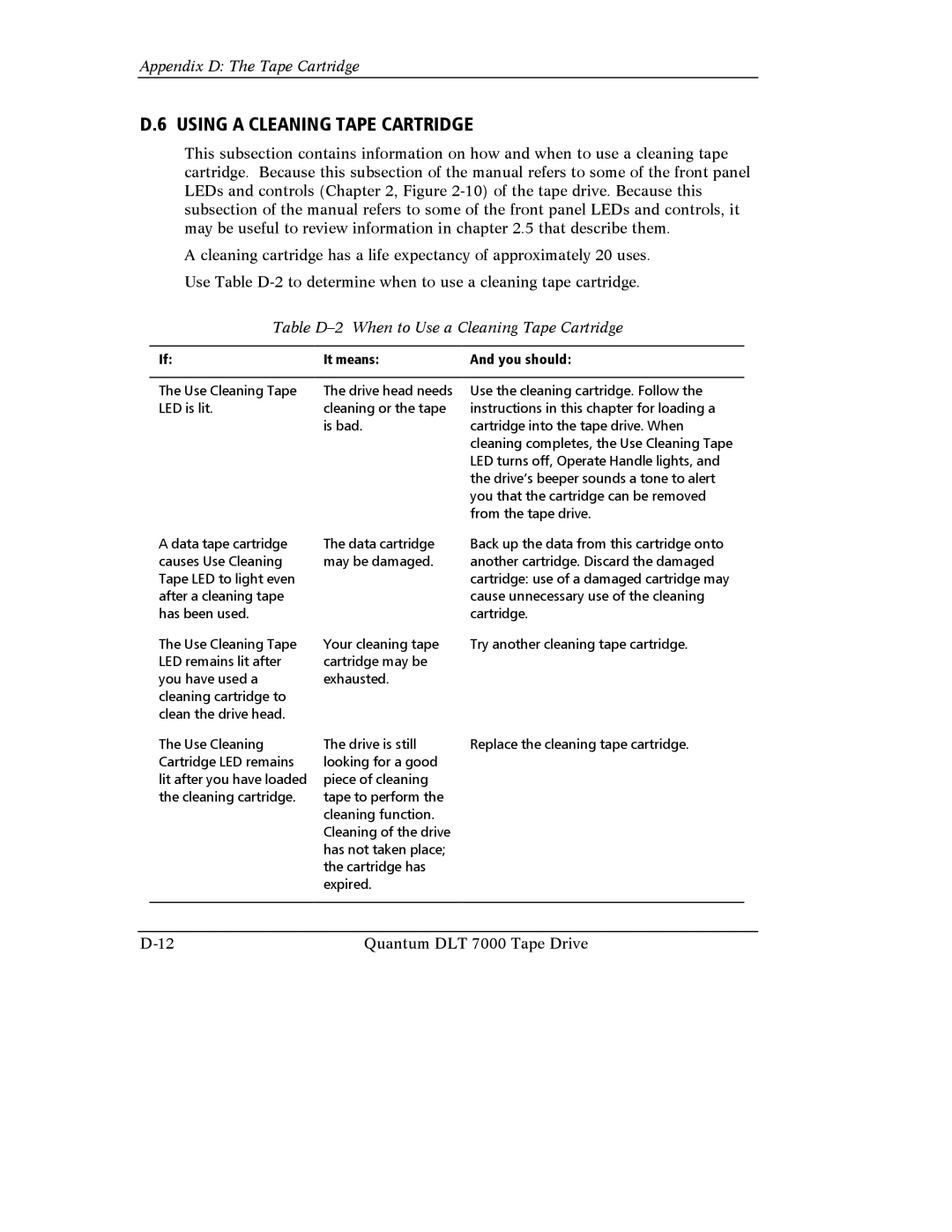
Using a Cleaning Tape Cartridge
Table D-2 When to Use a Cleaning Tape Cartridge
Index
Index
Eeprom
Scsi
Request SENSE, 5-156 Send Diagnostic
Index
Index-6 Quantum DLT 7000 Tape Drive
Page
81-60000-06 A02 Sycamore Drive Milpitas, CA 408