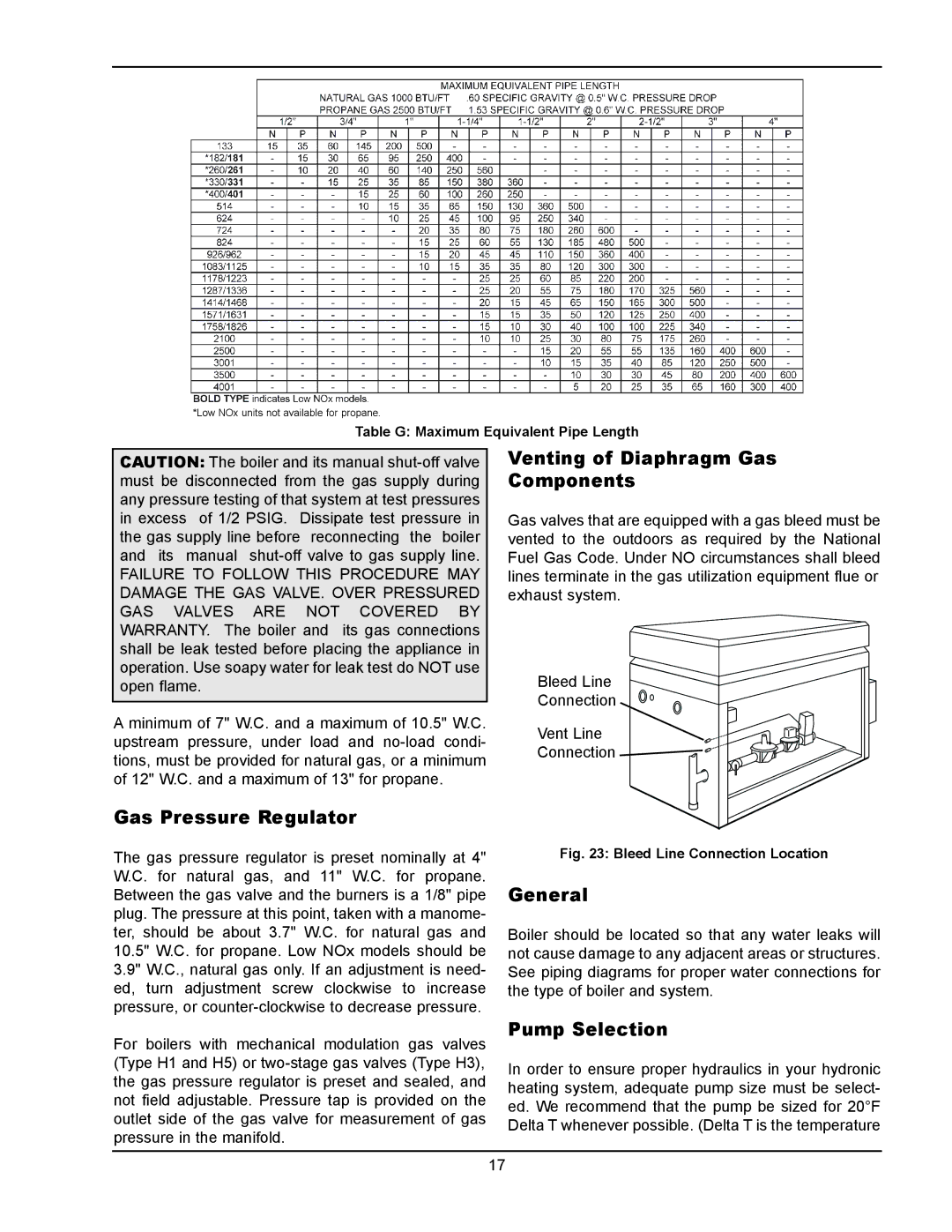
133-4001 specifications
Raypak 133-4001 is a premier heating solution designed for both residential and commercial applications, known for its efficiency and reliability. This high-performance water heater is specifically engineered to meet the demanding requirements of hot water supply while ensuring energy conservation and user convenience.One of the standout features of the Raypak 133-4001 is its robust construction. Made from high-quality materials, including a corrosion-resistant heat exchanger and durable casing, this unit is designed to withstand harsh environmental conditions. Its compact design allows for easy installation in various locations, making it an ideal choice for homeowners and businesses alike.
The unit operates on natural gas or LP gas, providing versatility in fuel choice. With a heating capacity of 199,000 BTU/hr, it delivers an impressive flow rate that ensures a steady supply of hot water, even during peak demand periods. This capacity makes it suitable for a wide range of applications, from residential water heating to larger facilities requiring substantial hot water output.
Raypak’s advanced technology set ensures that the 133-4001 operates at maximum efficiency. It utilizes a modulating power burner that adjusts the flame based on demand, optimizing fuel consumption. This feature not only helps in reducing energy bills but also minimizes the carbon footprint, making it an environmentally friendly option.
Another notable characteristic of the Raypak 133-4001 is its digital control system. The intuitive interface allows for precise temperature adjustments and easy monitoring of the heating process. Users can set the desired water temperature, and the system will maintain it consistently, ensuring comfort and reducing the risk of scalding.
Safety is a paramount consideration in the design of the 133-4001. It features a built-in high-limit switch, pressure relief valve, and multiple safety sensors to prevent overheating and potential hazards. These safety features provide peace of mind for homeowners and facility managers, knowing that their hot water system is reliable and secure.
In conclusion, Raypak 133-4001 combines advanced technology, robust construction, and user-friendly features, making it a highly effective water heating solution. Its efficiency and dependability cater to a variety of hot water needs, positioning it as a top choice for both residential and commercial use. Whether for a single-family home or a large facility, the Raypak 133-4001 is built to deliver exceptional performance with every use.

