INSTALLATION
6)FOR
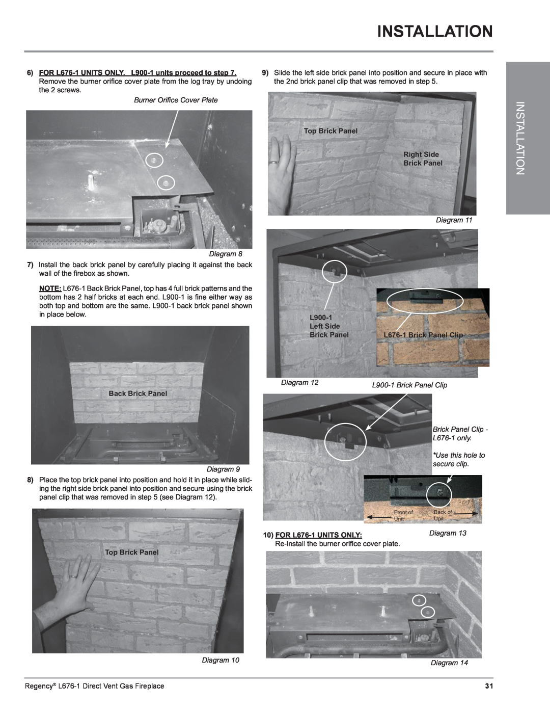
Burner Orifi ce Cover Plate
Diagram 8
7)Install the back brick panel by carefully placing it against the back wall of the fi rebox as shown.
NOTE:
9)Slide the left side brick panel into position and secure in place with the 2nd brick panel clip that was removed in step 5.
Top Brick Panel
Right Side
Brick Panel
Diagram 11
|
|
Left Side |
|
Brick Panel |
INSTALLATION
Diagram 12 | |
|
Back Brick Panel
Brick Panel Clip -
*Use this hole to
secure clip.
Diagram 9
8) Place the top brick panel into position and hold it in place while slid- ing the right side brick panel into position and secure using the brick panel clip that was removed in step 5 (see Diagram 12).
Front of | Back of |
Unit | Unit |
10) FOR | Diagram 13 |
|
Top Brick Panel
Diagram 10 | Diagram 14 |
|
Regency® | 31 |