INSTALLATION
FRAMING & FINISHING
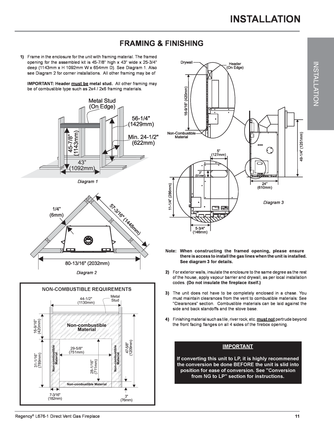
1)Frame in the enclosure for the unit with framing material. The framed
opening for the assembled kit is
IMPORTANT: Header must be metal stud. All other framing may be of combustible type such as 2x4 / 2x6 framing materials.
INSTALLATION
Diagram 1
Diagram 3
Diagram 2
Note: When constructing the framed opening, please ensure there is access to install the gas lines when the unit is installed. See diagram 3 for details.
2)For exterior walls, insulate the enclosure to the same degree as the rest of the house, apply vapour barrier and drywall, as per local installation codes. (Do not insulate the fireplace itself.)
3)The unit does not have to be completely enclosed in a chase. You must maintain clearances from the vent to combustible materials: See "Clearances" section. Combustible materials can be laid against the side and back standoffs and the stove base.
4)Finishing material such as tile, river rock, etc. must not pertrude beyond the front facing flanges on all 4 sides of the firebox opening.
IMPORTANT
If converting this unit to LP, it is highly recommened the conversion be done BEFORE the unit is slid into position for ease of conversion. See "Conversion from NG to LP" section for instructions.
Regency® | 11 |