| INSTALLATION |
|
|
| ||
| For USA installations follow local codes and/ | The manifold pressure is controlled by a regulator | ||||
| built into the gas control, and should be checked | |||||
| or the current National Fuel Gas Code, ANSI | |||||
|
| Canada | USA | at the pressure test point. | ||
|
| Z223.1. | ||||
INSTALLATION | Altitude | 0 - 2000 ft | 0 - 2000 ft | When using copper or flex connectors use only | Note: To properly check gas pressure, both | |
| (0 - 610m) | (0 - 610m) | ||||
|
| inlet and manifold pressures should | ||||
Min. Supply | 5" WC (1.25 | 5" WC | approved fittings. Always provide a union so |
| ||
| that gas lines can be easily disconnected for |
| be checked using the valve pressure | |||
| Pressure | kpa) | (1.25 kpa) | servicing. Flare nuts for copper lines and flex |
| ports on the valve. |
| Low Setting Man. | 1.6" WC | 1.6" WC | connectors are usually considered to meet this | 1) Make sure the valve is in the "OFF" | |
| Pressure | (0.39 kpa) | (0.39 kpa) | requirement. | ||
|
| position. | ||||
| Max. Manifold | 3.5" WC | 3.5" WC |
|
| |
|
|
|
| |||
| Pressure | (0.87 kpa) | (0.87 kpa) |
| 2) Loosen the "IN" and/or "OUT" pressure tap(s), | |
| Orifice Size | #33 DMS | #33 DMS |
|
| turning counterclockwise with a |
| Minimum Input | 22,000 Btu/h | 22,000 |
|
| 1/8" wide flat screwdriver. |
|
|
|
| |||
|
| (6.45 kW) | Btu/h |
| 3) | Attach manometer to "IN" and/or "OUT" |
|
|
| (6.45 kW) |
| ||
|
|
|
|
| pressure tap(s) using a 5/16" ID hose. | |
|
|
|
|
|
| |
| Maximum Input | 33,000 Btu/h | 33,000 |
| 4) | Light the pilot and turn the valve to "ON" |
|
| (9.67 kW) | Btu/h |
| ||
|
|
| (9.67 kW) |
|
| position. |
| Altitude |
| 5) | The pressure check should be carried out | ||
|
| ft. | ft. |
| ||
|
|
|
| with the unit burning and the setting should | ||
|
| (610- |
|
| ||
|
|
|
| be within the limits specified on the safety | ||
|
|
| 1371m) |
|
| |
|
|
| IMPORTANT: Always check for gas leaks |
| label. | |
| Orifice Size | #33 DMS | # 34 DMS |
| ||
| with a soap and water solution or gas leak | 6) | When finished reading manometer, turn off the | |||
| Minimum Input | 22,000 Btu/h | 21,500 | detector. Do not use open flame for leak | ||
| testing. |
| gas valve, disconnect the hose and tighten the | |||
|
| (6.45 kW) | Btu/h |
| ||
|
|
|
| screw (clockwise) with a 1/8" flat screwdriver. | ||
|
|
| (6.30 kW) |
|
| |
|
|
|
|
| Note: Screw should be snug, but do not | |
| Maximum Input | 33,000 Btu/h | 32,000 |
|
| |
|
|
| over tighten. | |||
|
| (9.67 kW) | Btu/h |
|
|
|
|
|
| (9.37kW) |
|
|
|
|
|
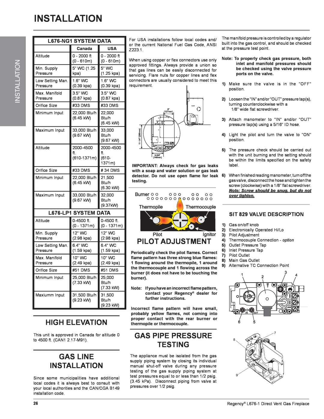
| SIT 829 VALVE DESCRIPTION | |||
| Altitude |
| 1) | Gas on/off knob | ||
|
| (0 - 1371m) | (0 - 1371m) |
| ||
| Min. Supply | 12" WC | 12" WC |
| 2) | Electronically Operated Hi/Lo |
|
| 3) | Pilot Adjustment | |||
| Pressure | (2.98 kpa) | (2.98 kpa) | PILOT ADJUSTMENT | ||
| 5) | Outlet Pressure Tap | ||||
| Low Setting Man. | 6.4" WC | 6.4" WC | |||
|
|
|
|
| 4) Thermocouple Connection - option | |
| Pressure | (1.59 kpa) | (1.59 kpa) | Periodically check the pilot flames. Correct | 6) | Inlet Pressure Tap |
| Max. Manifold | 10" WC | 10" WC | flame pattern has three strong blue flames: | 7) | Pilot Outlet |
| Pressure | (2.49 kpa) | (2.49 kpa) | 1 flowing around the thermopile, 1 around | 8) | Main Gas Outlet |
| Orifice Size | #51 DMS | #51 DMS | the thermocouple and 1 flowing across the | 9) | Alternative TC Connection Point |
| burner (it does not have to be touching the |
|
| |||
| Minimum Input | 25,000 Btu/h | 25,000 |
|
| |
| burner). |
|
| |||
|
| (7.33 kW) | Btu/h |
|
|
|
|
|
| (7.33 kW) | Note: If you have an incorrect flame pattern, |
|
|
| Maxiumm Input | 31,500 Btu/h | 31,500 | contact your Regency® dealer for |
|
|
| further instructions. |
|
| |||
|
| (9.23 kW) | Btu/h |
|
| |
|
|
| (9.23 kW) | Incorrect flame pattern will have small, |
|
|
|
|
|
|
|
| |
|
|
|
| probably yellow flames, not coming into |
|
|
| HIGH ELEVATION | proper contact with the rear burner or |
|
| ||
| thermopile or thermocouple. |
|
| |||
This unit is approved in Canada for altitude 0 | GAS PIPE PRESSURE |
| |
to 4500 ft. (CAN1 | TESTING |
|
GAS LINE
INSTALLATION
Since some municipalities have additional local codes it is always best to consult with your local authorities and the CAN/CGA B149 installation code.
The appliance must be isolated from the gas supply piping system by closing its individual manual
26 | Regency® |