INSTALLATION
VENTING ARRANGEMENTS
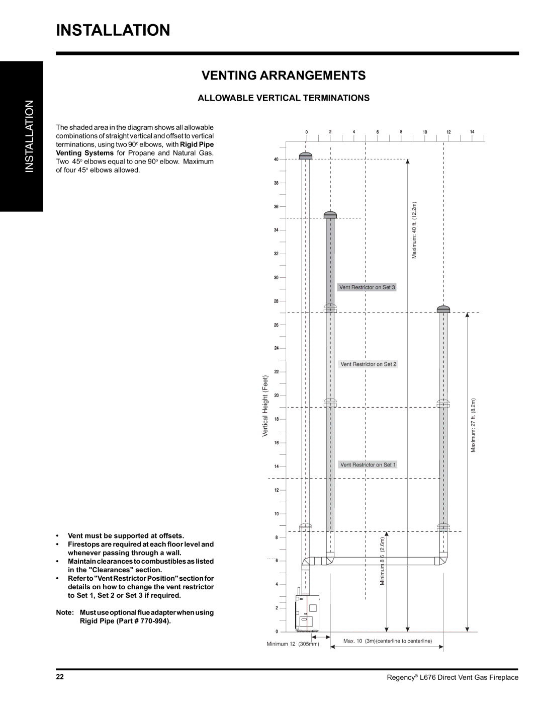
ALLOWABLE VERTICAL TERMINATIONS
INSTALLATION
The shaded area in the diagram shows all allowable combinations of straight vertical and offset to vertical terminations, using two 90o elbows, with Rigid Pipe Venting Systems for Propane and Natural Gas. Two 45o elbows equal to one 90o elbow. Maximum of four 45o elbows allowed.
•Vent must be supported at offsets.
•Firestops are required at each floor level and whenever passing through a wall.
•Maintainclearancestocombustiblesaslisted in the "Clearances" section.
•Referto"VentRestrictorPosition"sectionfor details on how to change the vent restrictor to Set 1, Set 2 or Set 3 if required.
Note: Mustuseoptionalflueadapterwhenusing Rigid Pipe (Part #
0
| 40 | |
| 38 | |
| 36 | |
| 34 | |
| 32 | |
| 30 | |
| 28 | |
| 26 | |
| 24 | |
(Feet) | 22 | |
20 | ||
Height | ||
| ||
Vertical | 18 | |
| 16 |
14
12
10
8
6
4
2
0
Minimum 12” (305mm)
2 | 4 | 6 | 8 | 10 | 12 | 14 |
Maximum: 40 ft. (12.2m)
Vent Restrictor on Set 3
Vent Restrictor on Set 2
Maximum: 27 ft. (8.2m)
Vent Restrictor on Set 1
Minimum 8’6” (2.6m)
Max. 10’ (3m)(centerline to centerline)
22 | Regency® L676 Direct Vent Gas Fireplace |