INSTALLATION

UNIT INSTALLATION

HORIZONTAL TERMINATION WITH FLEX VENT SYSTEM

Note: A top clearance of 3"(76mm) and side & bottom clearance of 2"(51mm) must be maintained; except when passing through a wall, ceiling, or at the termination where the use of a firestop or wall thimble reduces the required clearance to 1-1/2" (38mm). Werecommendframinga11"(279mm) x 11"(279mm) (inside dimensions) hole to give structural rigidity for mounting the termination.

1)Locate the unit in the framing, rough in the gas (preferably on the right side of the unit) and the electrical (Junction block is on the left side) on the left. Locate the centerline of the termination and mark wall accordingly. Cut an 11"(279mm) hole in the wall (inside dimension).

Note: If installing termination on a siding covered wall, a vinyl siding standoff or vinyl furring strips must be used to ensure that the termination is not recessed into the siding.

2)Level the fi replace and fasten it to the fram- ing using nails or screws through the nailing strips.

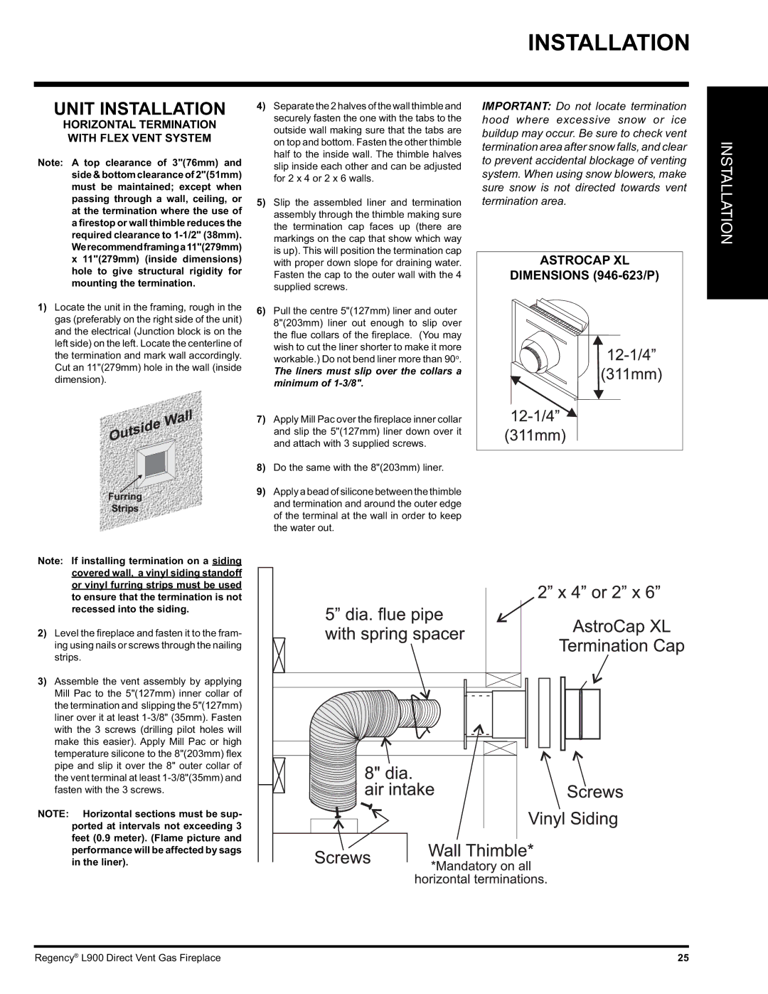
3)Assemble the vent assembly by applying Mill Pac to the 5"(127mm) inner collar of the termination and slipping the 5"(127mm) liner over it at least 1-3/8" (35mm). Fasten with the 3 screws (drilling pilot holes will make this easier). Apply Mill Pac or high temperature silicone to the 8"(203mm) fl ex pipe and slip it over the 8" outer collar of the vent terminal at least 1-3/8"(35mm) and fasten with the 3 screws.

NOTE: Horizontal sections must be sup- ported at intervals not exceeding 3 feet (0.9 meter). (Flame picture and performance will be affected by sags in the liner).

4)Separate the 2 halves of the wall thimble and securely fasten the one with the tabs to the outside wall making sure that the tabs are on top and bottom. Fasten the other thimble half to the inside wall. The thimble halves slip inside each other and can be adjusted for 2 x 4 or 2 x 6 walls.

5)Slip the assembled liner and termination assembly through the thimble making sure the termination cap faces up (there are markings on the cap that show which way is up). This will position the termination cap with proper down slope for draining water. Fasten the cap to the outer wall with the 4 supplied screws.

6)Pull the centre 5"(127mm) liner and outer 8"(203mm) liner out enough to slip over the fl ue collars of the fi replace. (You may wish to cut the liner shorter to make it more workable.) Do not bend liner more than 90o.

The liners must slip over the collars a minimum of 1-3/8".

7)Apply Mill Pac over the fi replace inner collar and slip the 5"(127mm) liner down over it and attach with 3 supplied screws.

8)Do the same with the 8"(203mm) liner.

9)Apply a bead of silicone between the thimble and termination and around the outer edge of the terminal at the wall in order to keep the water out.

IMPORTANT: Do not locate termination hood where excessive snow or ice buildup may occur. Be sure to check vent termination area after snow falls, and clear to prevent accidental blockage of venting system. When using snow blowers, make sure snow is not directed towards vent termination area.

ASTROCAP XL

DIMENSIONS (946-623/P)

INSTALLATION

Regency® L900 Direct Vent Gas Fireplace

25

Page 25
Image 25
Regency L900-NG, L900-LP installation manual Unit Installation, Astrocap XL

L900-LP, L900-NG specifications

The Regency L900-NG and L900-LP are remarkable gas fireplaces that epitomize both elegance and efficiency, bringing a blend of modern technology and traditional aesthetics to any living space. Designed for versatility, these units are suitable for homes with natural gas (NG) or propane (LP) gas lines, thus catering to a wide range of customer preferences.

One of the standout features of the L900 series is its impressive heating capacity. With up to 30,000 BTUs, these fireplaces can efficiently warm large areas, making them an exceptional choice for both residential and commercial settings. Their exceptional airflow and heat distribution ensure that users enjoy a cozy ambience throughout the space.

The L900 models are integrated with cutting-edge technology that enhances user experience. The advanced electronic ignition ensures reliable start-ups, while the variable flame height adjustment provides flexibility, allowing users to customize the heat output according to their needs. The inclusion of an optional remote control system adds an extra layer of convenience, enabling homeowners to operate the fireplace from anywhere in the room.

Aesthetic appeal is also a major highlight of the Regency L900 series. The full-view glass front maximizes the viewing area, allowing users to enjoy the mesmerizing flames fully. The sleek, contemporary design can easily complement various interior styles, from modern to traditional settings. Moreover, with several customizable options, including media choices such as glass, pebbles, or logs, users can personalize their fireplace to suit their decor.

Safety is always a priority with Regency products. The L900 models come equipped with a safety shut-off valve that activates in case of any irregularities, providing peace of mind for users. Additionally, the fireplace’s direct venting system ensures that combustion gases are safely expelled outside, allowing for effective ventilation without compromising indoor air quality.

Durability is another significant characteristic of the Regency L900 series. Constructed from high-quality materials, these fireplaces promise longevity and resilience, ensuring they can withstand the test of time.

Overall, the Regency L900-NG and L900-LP gas fireplaces stand out for their combination of performance, efficiency, and style. With their advanced features, customizable options, and focus on safety, they provide an enticing heating solution for any home or business, merging warmth with a touch of elegance.