Characteristics (cont.)
The table opposite serves as an example for an installation comprising up to four frequency converters or four parallel UPSs with a centralised SSC.
◗for installations with redundant units, take into account only the units required to supply the load power (e.g. for an installation made up of 3
◗this table has been drawn up for rated
The cable
Parameters for Mains 2 and load cables for an installation comprising frequency converters or parallel UPSs with a centralised SSC.
rated inverter | number of | total UPS | Mains 2 or load | cable | |
output |
| rated output | line current | in mm2 |
|
in kVA | inverters | in kVA | in Amps | Copper | Aluminium |
250 | 2 | 500 | 722 | 2 x 185 | 2 x 300 |
| 3 | 750 | 1082 | 3 x 300 | 4 x 240 |
| 4 | 1000 | 1444 | 4 x 240 | 4 x 400 |
300 | 2 | 600 | 866 | 2 x 240 | 4 x 185 |
| 3 | 900 | 1299 | 4 x 240 | 4 x 400 |
| 4 | 1200 | 1732 | Please consult us* | |
400 | 2 | 800 | 1298 | 4 x 185 | 4 x 300 |
| 3 | 1200 | 1947 | Please consult us* | |
| 4 | 1600 | 2596 | Please consult us* | |
|
|
|
|
|
|
450 | 2 | 900 | 1154 | 4 x 240 | 4 x 400 |
| 3 | 1350 | 1731 | Please consult us* | |
| 4 | 1800 | 2308 | Please consult us* | |
|
|
|
|
|
|
500 | 2 | 1000 | 1444 | 4 x 240 | 4 x 400 |
| 3 | 1500 | 2164 | Please consult us* | |
| 4 | 2000 | 2888 | Please consult us* | |
600 | 2 | 1200 | 1731 | Please consult us* | |
| 3 | 1800 | 2598 | Please consult us* | |
| 4 | 2400 | 3462 | Please consult us* | |
(1) cable | maximum length of 100 m. For greater lengths, |
conductors of the U1000 R02V type. They are | the |
calculated according to permissible temperature | voltage drops to 3%. |
rise and allow for line voltage drops over a |
|
NF C
Installation with parallel frequency converters
mains 1
inverter 1
mains 1
inverter 2
![]() load
load
mains 1
inverter 3
Fig. 1
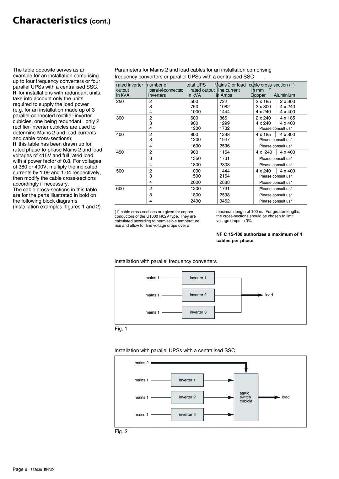
Installation with parallel UPSs with a centralised SSC
mains 2
mains 1
mains 1
inverter 1
inverter 2
static switch cubicle
![]() load
load
mains 1
inverter 3
Fig. 2
Page 8 - 6739381EN/JD