Installation (cont.)
Connections between ACPZ boards (frequency converters or parallel UPSs with SSC)
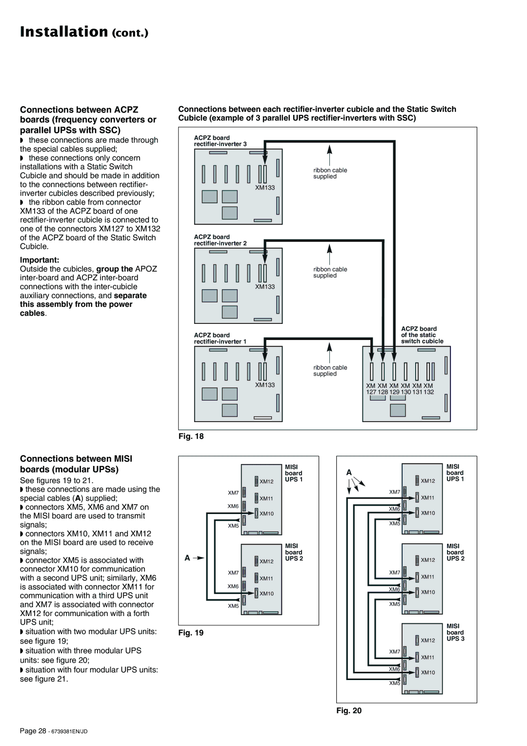
◗these connections are made through the special cables supplied;
◗these connections only concern installations with a Static Switch Cubicle and should be made in addition to the connections between rectifier- inverter cubicles described previously;
◗the ribbon cable from connector XM133 of the ACPZ board of one
Important:
Outside the cubicles, group the APOZ
Connections between each
ACPZ board |
|
| |
| ribbon cable |
| supplied |
XM133 |
|
ACPZ board |
|
| |
| ribbon cable |
| supplied |
XM133 |
|
| ACPZ board |
ACPZ board | of the static |
switch cubicle | |
| ribbon cable |
| supplied |
XM133 | XM XM XM XM XM XM |
| 127 128 129 130 131 132 |
Fig. 18
Connections between MISI boards (modular UPSs)
See figures 19 to 21.
◗these connections are made using the special cables (A) supplied;
◗connectors XM5, XM6 and XM7 on the MISI board are used to transmit signals;
◗connectors XM10, XM11 and XM12 on the MISI board are used to receive signals;
◗connector XM5 is associated with connector XM10 for communication with a second UPS unit; similarly, XM6 is associated with connector XM11 for communication with a third UPS unit and XM7 is associated with connector XM12 for communication with a forth UPS unit;
◗situation with two modular UPS units: see figure 19;
◗situation with three modular UPS units: see figure 20;
◗situation with four modular UPS units: see figure 21.
|
| MISI |
|
| board |
| XM12 | UPS 1 |
|
| |
| XM7 |
|
| XM11 |
|
| XM6 |
|
| XM10 |
|
| XM5 |
|
|
| MISI |
A |
| board |
XM12 | UPS 2 | |
|
| |
| XM7 |
|
| XM11 |
|
| XM6 |
|
| XM10 |
|
| XM5 |
|
Fig. 19
A |
| MISI |
| board | |
| XM12 | UPS 1 |
XM7 | XM11 |
|
|
| |
XM6 | XM10 |
|
|
| |
XM5 |
|
|
|
| MISI |
|
| board |
| XM12 | UPS 2 |
XM7 | XM11 |
|
|
| |
XM6 | XM10 |
|
|
| |
XM5 |
|
|
|
| MISI |
|
| board |
| XM12 | UPS 3 |
XM7 | XM11 |
|
|
| |
XM6 | XM10 |
|
|
| |
XM5 |
|
|
Fig. 20
Page 28 - 6739381EN/JD