Installation (cont.)
Connection of the battery "Temperature Monitor" (optional)
Connections
This unit must be connected to connector XR4 of the remote relay board of the
◗ use a shielded cable made up of 2 |
twisted telephone pairs with a |
conductor |
0.1 mm2 and up to 100 m in length; |
◗ do not forget to connect the cable |
shield to ground pin 7 of connector |
XR4; |
◗ in the case of a parallel UPS |
configuration, the connections between |
cubicles may be made by means of a |
shielded cable made up of 1 or 2 |
twisted telephone pairs. In this case, |
the total length of all the connecting |
cables should not exceed 100 m; |
◗ a "Temperature Monitor" can only be |
connected to several |
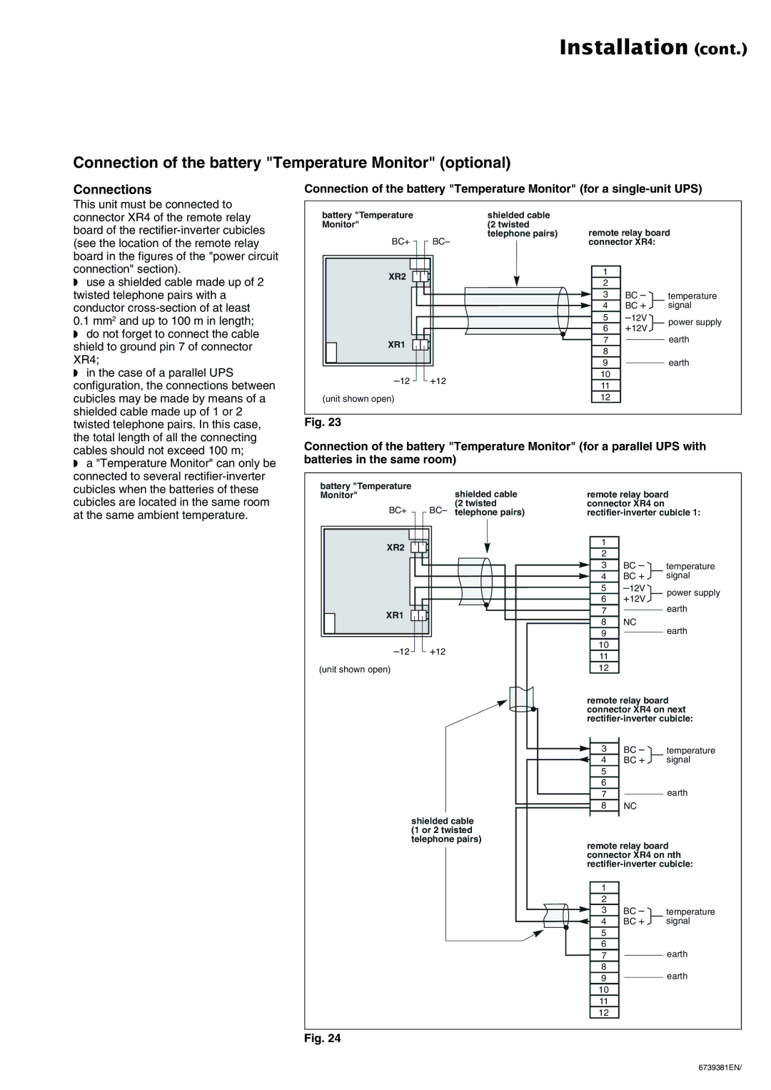
Connection of the battery "Temperature Monitor" (for a
battery "Temperature | shielded cable |
|
|
|
Monitor" | (2 twisted | remote relay board | ||
| telephone pairs) | |||
BC+ | BC– | connector XR4: |
| |
XR2 |
| 1 |
|
|
| 2 |
|
| |
|
|
|
| |
|
| 3 | BC – | temperature |
|
| 4 | BC + | signal |
|
| 5 | power supply | |
|
| 6 | +12V | |
|
|
| ||
XR1 |
| 7 |
| earth |
| 8 |
|
| |
|
|
|
| |
|
| 9 |
| earth |
+12 | 10 |
|
| |
11 |
|
| ||
|
|
|
| |
(unit shown open) |
| 12 |
|
|
Fig. 23
Connection of the battery "Temperature Monitor" (for a parallel UPS with batteries in the same room)
cubicles when the batteries of these |
cubicles are located in the same room |
at the same ambient temperature. |
battery "Temperature Monitor"
BC+
XR2
XR1
(unit shown open)
shielded cable (2 twisted
BC– telephone pairs)
+12
remote relay board connector XR4 on
1 |
|
| |
2 |
|
| |
3 | BC – | temperature | |
4 | BC + | signal | |
5 | power supply | ||
6 | +12V | ||
|
7earth
8NC
9earth
10
11
12
remote relay board connector XR4 on next
3 | BC – | temperature | |
4 | BC + | signal | |
5 |
|
|
|
6 |
|
|
|
7 |
|
| earth |
|
| ||
8 | NC |
| |
|
|
|
|
shielded cable (1 or 2 twisted
telephone pairs)
remote relay board connector XR4 on nth
1 |
|
|
|
2 |
|
|
|
3 | BC – | temperature | |
4 | BC + | signal | |
5 |
|
|
|
6 |
|
| earth |
7 |
|
| |
|
| ||
8 |
|
| earth |
9 |
|
| |
|
| ||
10 |
|
|
|
11 |
|
|
|
12 |
|
|
|
Fig. 24
6739381EN/