Installation (cont.)
Configuration of the AS/400→
Certain values on the AS/400→ must be configured to enable operation of the MGETM GalaxyTM 6000 AS/400→ link.
The values requiring modification and the corresponding procedures are presented in chapter 7 "Power Loss Recovery" of the
The values are the following:
◗ QUPSMSGQ UPS message Queue;
◗QUPSDLYTIM Uninterruptible Power Supply Delay Time;
◗QPWRRSTIPL Power Restore IPL.
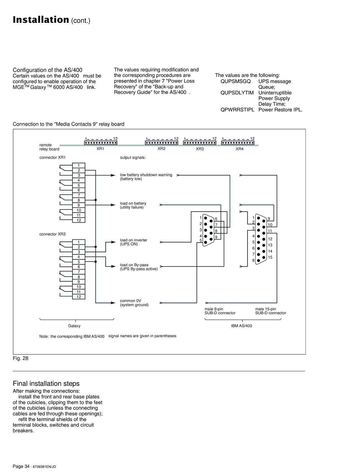
Connection to the "Media Contacts 9" relay board
1 | 12 | 1 | 12 | 1 | 12 | 1 | 12 |
|
remote | XR1 | XR2 |
| XR3 |
|
| XR4 |
|
relay board |
|
|
|
| ||||
connector XR1 |
| output signals: |
|
|
|
|
|
|
1 |
|
|
|
|
|
|
|
|
2 |
| low battery shutdown warning |
|
|
|
|
|
|
3 |
|
|
|
|
|
|
| |
4 |
| (battery low) |
|
|
|
|
|
|
|
|
|
|
|
|
|
| |
5 |
|
|
|
|
|
|
|
|
6 |
|
|
|
|
|
|
|
|
7 |
|
|
|
|
|
|
|
|
8 |
| load on battery |
|
|
|
|
|
|
9 |
|
|
|
|
|
|
| |
| (utility failure) |
|
|
|
|
|
| |
10 |
|
|
|
|
|
|
| |
|
|
|
|
|
|
|
| |
11 |
|
|
| 1 | 6 |
| 1 | 9 |
12 |
|
|
|
| ||||
|
|
| 2 |
|
| 2 |
| |
|
|
|
| 7 |
| 10 | ||
|
|
|
|
| 3 | |||
|
|
|
| 3 | 8 |
| 11 | |
connector XR2 |
|
|
|
|
| |||
|
|
| 4 | 9 |
| 4 |
| |
|
| load on inverter |
|
| 12 | |||
|
|
| 5 |
|
| |||
1 |
|
|
|
| 5 | |||
| (UPS ON) |
|
|
|
| 13 | ||
2 |
|
|
|
|
| 6 | ||
|
|
|
|
|
| 14 | ||
3 |
|
|
|
|
|
| ||
|
|
|
|
|
| 7 | ||
4 |
|
|
|
|
|
| 15 | |
|
|
|
|
|
| 8 | ||
5 |
| load on |
|
|
|
|
| |
|
|
|
|
|
|
| ||
6 |
|
|
|
|
|
|
| |
| (UPS |
|
|
|
|
|
| |
7 |
|
|
|
|
|
|
| |
|
|
|
|
|
|
|
| |
8 |
|
|
|
|
|
|
|
|
9 |
|
|
|
|
|
|
|
|
10 |
|
|
|
|
|
|
|
|
11 |
|
|
|
|
|
|
|
|
12 |
| common 0V |
|
|
|
|
|
|
|
|
|
|
|
|
|
| |
|
| (system ground) |
|
| male |
| male | |
|
|
|
|
|
| |||
|
|
|
|
| ||||
Galaxy |
|
|
|
|
|
| IBM AS/400→ |
|
Note: the corresponding IBM AS/400→ signal names are given in parentheses |
|
|
|
|
| |||
Fig. 28
Final installation steps
After making the connections:
◗install the front and rear base plates of the cubicles, clipping them to the feet of the cubicles (unless the connecting cables are fed through these openings);
◗refit the terminal shields of the terminal blocks, switches and circuit breakers.
Page 34 - 6739381EN/JD