Characteristics (cont.)
Electrical parameters for determining cable cross-sections
◗this table has been drawn up for rated
◗the current values and cable cross- sections for Mains 1 are given for full rated load with a power factor of 0.8 and a battery consuming its minimum float charging voltage;
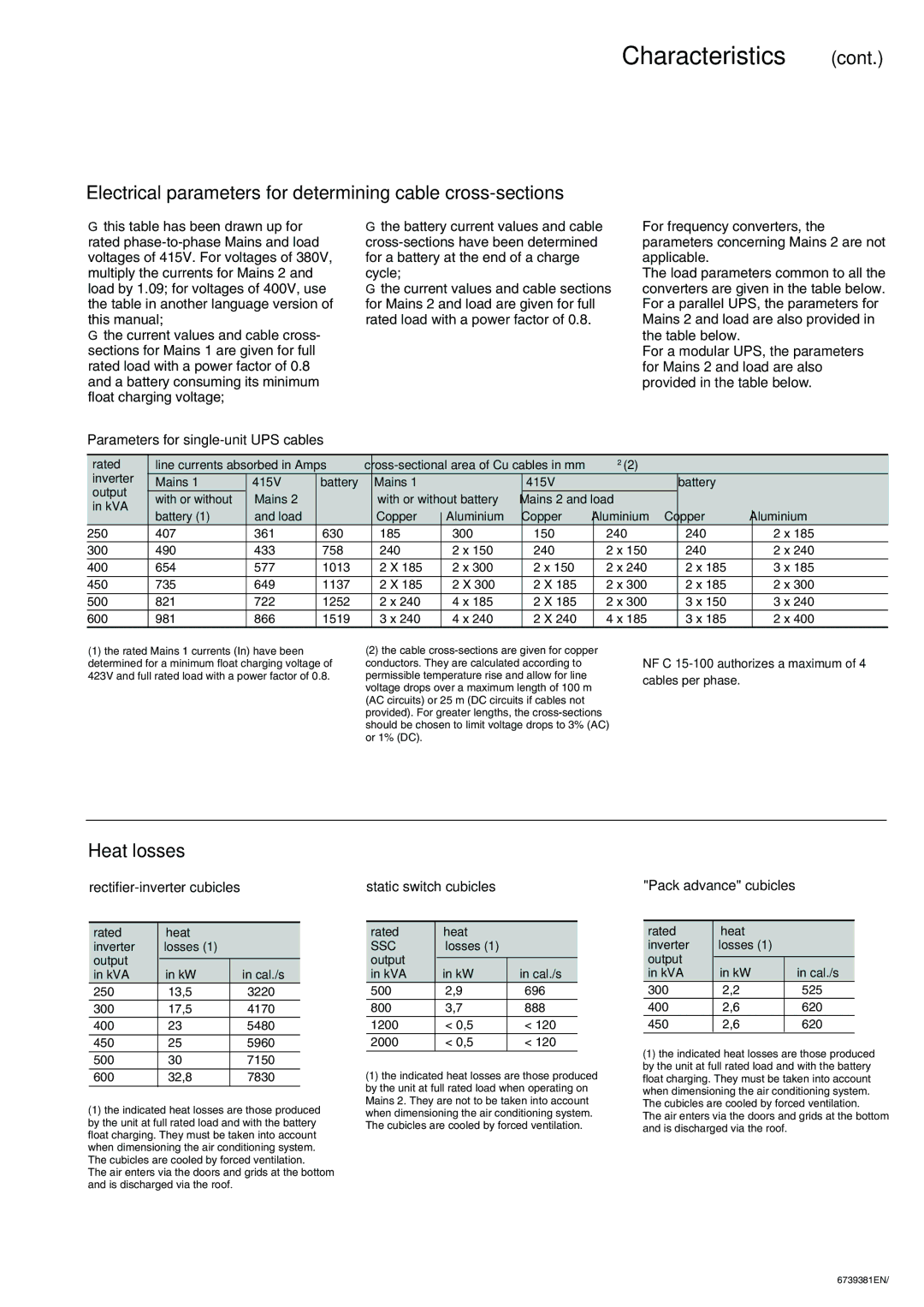
Parameters for single-unit UPS cables
◗the battery current values and cable
◗the current values and cable sections for Mains 2 and load are given for full rated load with a power factor of 0.8.
For frequency converters, the parameters concerning Mains 2 are not applicable.
The load parameters common to all the converters are given in the table below. For a parallel UPS, the parameters for Mains 2 and load are also provided in the table below.
For a modular UPS, the parameters for Mains 2 and load are also provided in the table below.
rated | line currents absorbed in Amps |
|
| ||||||
inverter | Mains 1 | 415V | battery | Mains 1 |
| 415V |
| battery |
|
output | with or without | Mains 2 |
| with or without battery | Mains 2 and load |
|
| ||
in kVA |
|
|
| ||||||
| battery (1) | and load |
| Copper | Aluminium | Copper | Aluminium | Copper | Aluminium |
250 | 407 | 361 | 630 | 185 | 300 | 150 | 240 | 240 | 2 x 185 |
300 | 490 | 433 | 758 | 240 | 2 x 150 | 240 | 2 x 150 | 240 | 2 x 240 |
400 | 654 | 577 | 1013 | 2 X 185 | 2 x 300 | 2 x 150 | 2 x 240 | 2 x 185 | 3 x 185 |
450 | 735 | 649 | 1137 | 2 X 185 | 2 X 300 | 2 X 185 | 2 x 300 | 2 x 185 | 2 x 300 |
|
|
|
|
|
|
|
|
|
|
500 | 821 | 722 | 1252 | 2 x 240 | 4 x 185 | 2 X 185 | 2 x 300 | 3 x 150 | 3 x 240 |
600 | 981 | 866 | 1519 | 3 x 240 | 4 x 240 | 2 X 240 | 4 x 185 | 3 x 185 | 2 x 400 |
(1)the rated Mains 1 currents (In) have been determined for a minimum float charging voltage of 423V and full rated load with a power factor of 0.8.
(2)the cable
NF C
Heat losses
rectifier-inverter cubicles
rated | heat |
|
inverter | losses (1) |
|
output |
|
|
|
| |
in kVA | in kW | in cal./s |
250 | 13,5 | 3220 |
300 | 17,5 | 4170 |
400 | 23 | 5480 |
|
|
|
450 | 25 | 5960 |
500 | 30 | 7150 |
600 | 32,8 | 7830 |
|
|
|
(1)the indicated heat losses are those produced by the unit at full rated load and with the battery float charging. They must be taken into account when dimensioning the air conditioning system. The cubicles are cooled by forced ventilation.
The air enters via the doors and grids at the bottom and is discharged via the roof.
static switch cubicles
rated | heat |
|
SSC | losses (1) |
|
output |
|
|
|
| |
in kVA | in kW | in cal./s |
500 | 2,9 | 696 |
800 | 3,7 | 888 |
1200 | < 0,5 | < 120 |
2000 | < 0,5 | < 120 |
|
|
|
(1)the indicated heat losses are those produced by the unit at full rated load when operating on Mains 2. They are not to be taken into account when dimensioning the air conditioning system. The cubicles are cooled by forced ventilation.
"Pack advance" cubicles
rated | heat |
|
inverter | losses (1) |
|
output |
|
|
|
| |
in kVA | in kW | in cal./s |
300 | 2,2 | 525 |
400 | 2,6 | 620 |
450 | 2,6 | 620 |
(1)the indicated heat losses are those produced by the unit at full rated load and with the battery float charging. They must be taken into account when dimensioning the air conditioning system. The cubicles are cooled by forced ventilation.
The air enters via the doors and grids at the bottom and is discharged via the roof.
6739381EN/