Appendix (cont.)
Cubicle mounting and connection for 600kVA UPSs
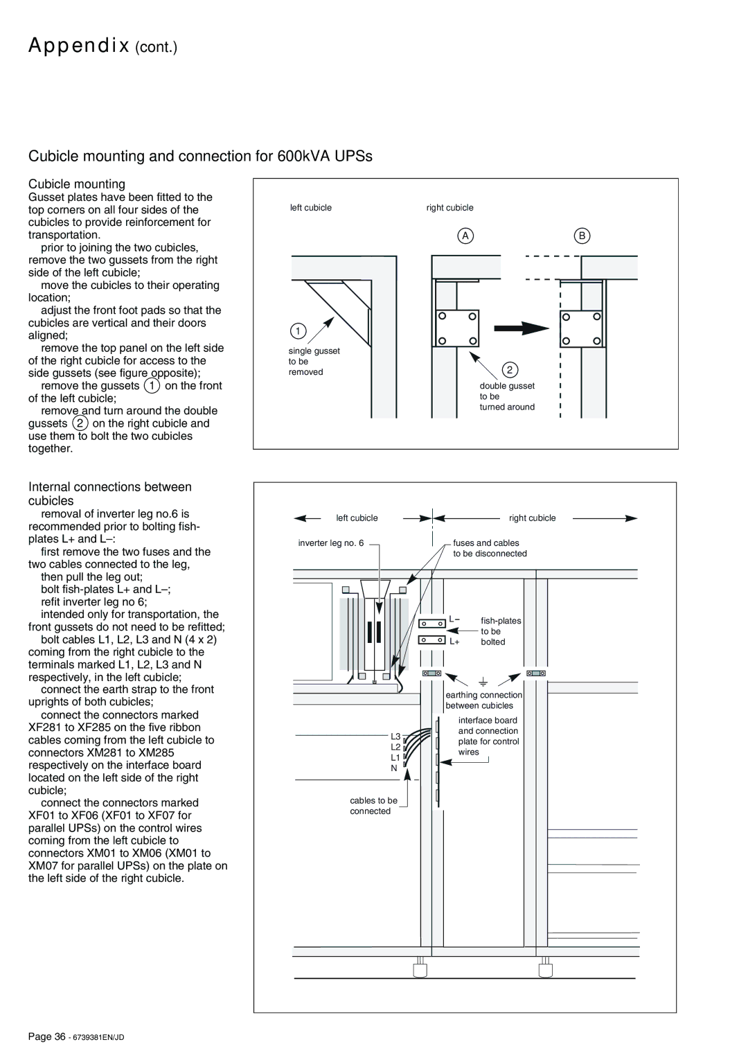
Cubicle mounting
Gusset plates have been fitted to the top corners on all four sides of the cubicles to provide reinforcement for transportation.
◗prior to joining the two cubicles, remove the two gussets from the right side of the left cubicle;
◗move the cubicles to their operating location;
◗adjust the front foot pads so that the cubicles are vertical and their doors aligned;
◗remove the top panel on the left side of the right cubicle for access to the side gussets (see figure opposite);
◗remove the gussets 1 on the front of the left cubicle;
◗remove and turn around the double gussets 2 on the right cubicle and use them to bolt the two cubicles together.
left cubicle
1 |
single gusset |
to be |
removed |
right cubicle
A | B |
| 2 |
| double gusset |
| to be |
| turned around |
Internal connections between cubicles
◗removal of inverter leg no.6 is recommended prior to bolting fish- plates L+ and
◗first remove the two fuses and the two cables connected to the leg,
◗then pull the leg out;
◗bolt
◗refit inverter leg no 6;
◗intended only for transportation, the front gussets do not need to be refitted;
◗bolt cables L1, L2, L3 and N (4 x 2) coming from the right cubicle to the terminals marked L1, L2, L3 and N respectively, in the left cubicle;
◗connect the earth strap to the front uprights of both cubicles;
◗connect the connectors marked XF281 to XF285 on the five ribbon cables coming from the left cubicle to connectors XM281 to XM285 respectively on the interface board located on the left side of the right cubicle;
◗connect the connectors marked XF01 to XF06 (XF01 to XF07 for parallel UPSs) on the control wires coming from the left cubicle to connectors XM01 to XM06 (XM01 to XM07 for parallel UPSs) on the plate on the left side of the right cubicle.
left cubicle |
| right cubicle | |
inverter leg no. 6 | fuses and cables | ||
| to be disconnected | ||
| L | ||
| L+ | to be | |
| bolted | ||
| earthing connection | ||
| between cubicles | ||
| interface board | ||
L3 | and connection | ||
plate for control | |||
L2 | |||
wires |
| ||
L1 |
| ||
|
| ||
N |
|
| |
cables to be |
|
| |
connected |
|
| |
Page 36 - 6739381EN/JD