Installation (cont.)
Connection of the "LED" remote indications unit
This unit is connected to connectors XR1 and XR2 of the remote relay boards of the
For the installation of the unit and details of connections at the unit end, see the instructions delivered with the unit nr 5102990400.
◗recommended cable
Connection of "Tele Monitor" remote control and indication unit (option)
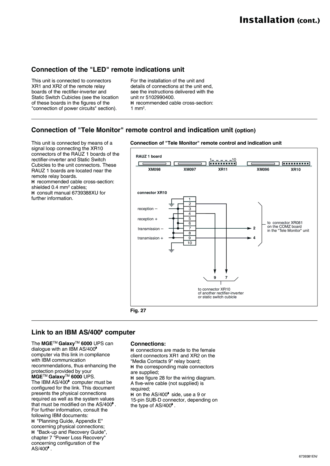
This unit is connected by means of a signal loop connecting the XR10 connectors of the RAUZ 1 boards of the
◗recommended cable
◗consult manual 6739388XU for further information.
Connection of "Tele Monitor" remote control and indication unit
RAUZ 1 board | 1 | 10 |
|
|
|
|
|
|
| ||
XM098 | XM097 | XR11 |
| XM096 | XR10 |
connector XR10 |
|
|
|
|
|
| 1 |
|
|
|
|
reception – | 2 |
|
|
|
|
3 |
|
|
|
| |
| 4 |
|
|
|
|
reception + | 5 |
|
| to connector XR081 | |
| 6 |
|
| ||
transmission – | 7 |
| 2 | on the COMZ board | |
| in the "Tele Monitor" unit | ||||
| 8 |
|
| ||
|
|
|
|
| |
transmission + | 9 |
| 4 |
|
|
| 10 |
|
|
|
|
| 9 | 7 |
|
|
|
| to connector XR10 |
|
|
| |
| of another |
|
|
| |
| or static switch cubicle |
|
|
| |
Fig. 27
Link to an IBM AS/400→ computer
The MGETM GalaxyTM 6000 UPS can dialogue with an IBM AS/400→ computer via this link in compliance with IBM communication recommendations, thus enhancing the protection provided by your
MGETM GalaxyTM 6000 UPS.
The IBM AS/400→ computer must be configured for the link. This document presents the physical connections required as well as the system values that must be modified on the AS/400→. For further information, consult the following IBM documents:
◗"Planning Guide, Appendix E" concerning physical connections;
◗
concerning configuration of the AS/400→.
Connections:
◗connections are made to the female client connectors XR1 and XR2 on the "Media Contacts 9" relay board;
◗the corresponding male connectors are supplied;
◗see figure 28 for the wiring diagram. A
◗on the AS/400→ side, use a 9 or
6739381EN/