Installation (cont.)
◗on the floor under the cubicles, in the free space equal to the height of the feet. In this case the cables should be run side by side to avoid blocking the flow of air for ventilation. The cables exit from the rear or sides of the cubicles;
◗connection via the top
◗the Static Switch, filter and auxiliary cubicles are designed for connection via the bottom or top,
◗for the
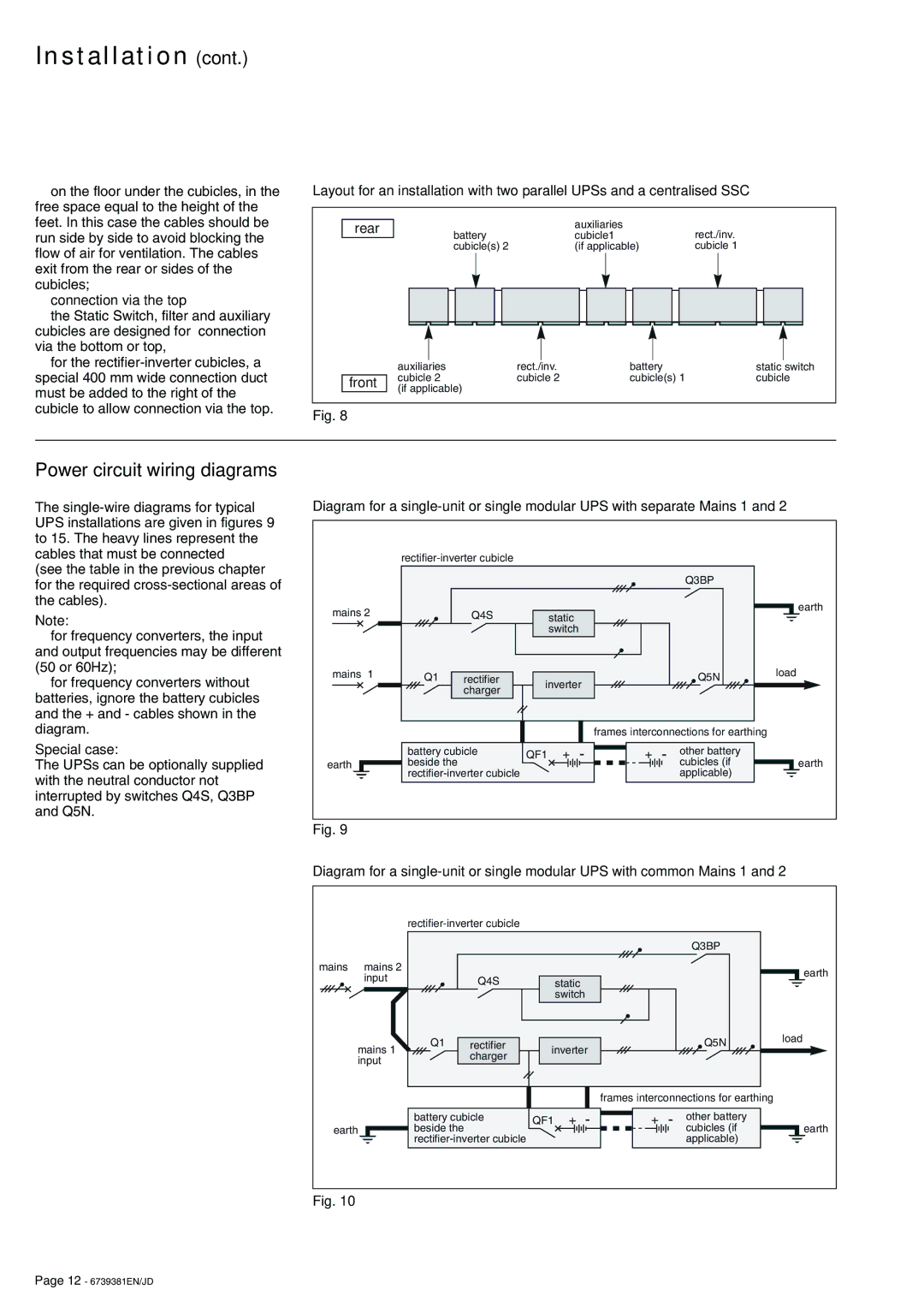
Layout for an installation with two parallel UPSs and a centralised SSC
rear | battery |
| auxiliaries | rect./inv. |
|
| cubicle1 | ||
| cubicle(s) 2 |
| (if applicable) | cubicle 1 |
| auxiliaries | rect./inv. | battery | static switch |
front | cubicle 2 | cubicle 2 | cubicle(s) 1 | cubicle |
(if applicable) |
|
|
| |
|
|
|
|
Fig. 8
Power circuit wiring diagrams
The
(see the table in the previous chapter for the required
Note:
◗for frequency converters, the input and output frequencies may be different (50 or 60Hz);
◗for frequency converters without batteries, ignore the battery cubicles and the + and - cables shown in the diagram.
Special case:
The UPSs can be optionally supplied with the neutral conductor not interrupted by switches Q4S, Q3BP and Q5N.
Diagram for a
|
|
|
|
|
|
|
|
|
| |
|
|
|
|
|
|
|
| Q3BP |
|
|
mains 2 |
| Q4S |
| static |
|
|
|
|
| earth |
|
|
|
|
|
|
|
| |||
|
|
|
| switch |
|
|
|
|
|
|
mains 1 | Q1 | rectifier | inverter |
|
| Q5N | load |
| ||
|
|
|
|
| ||||||
|
| charger |
|
|
|
|
| |||
|
|
|
|
|
|
|
|
|
| |
|
|
|
|
|
| frames interconnections for earthing |
| |||
| battery cubicle | QF1 | + | - | + | - | other battery |
|
| |
earth | beside the |
|
|
|
| cubicles (if |
| earth | ||
|
|
|
|
|
| applicable) |
|
| ||
Fig. 9
Diagram for a
|
|
|
|
|
|
|
|
|
| ||
|
|
|
|
|
|
|
|
| Q3BP |
|
|
mains | mains 2 |
|
|
|
|
|
|
|
|
| earth |
| input |
| Q4S |
| static |
|
|
|
|
| |
|
|
|
|
|
|
|
|
| |||
|
|
|
|
|
|
|
|
|
| ||
|
|
|
|
| switch |
|
|
|
|
|
|
mains 1 | Q1 | rectifier | inverter |
|
| Q5N | load |
| |||
|
|
|
| ||||||||
| charger |
|
|
|
|
| |||||
input |
|
|
|
|
|
|
|
|
| ||
|
|
|
|
|
|
|
|
|
| ||
|
|
|
|
|
|
| frames interconnections for earthing |
| |||
|
| battery cubicle | QF1 | + | - | + | - | other battery |
|
| |
earth |
| beside the |
|
|
|
|
|
| cubicles (if |
| earth |
|
|
|
|
|
|
| applicable) |
|
| ||
Fig. 10
Page 12 - 6739381EN/JD
