Installation (cont.)
Connection of power circuits
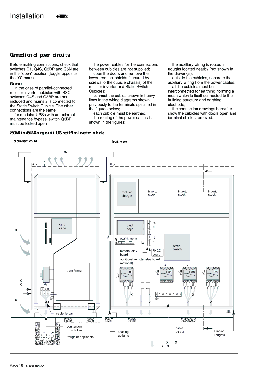
Before making connections, check that switches Q1, Q4S, Q3BP and Q5N are in the "open" position (toggle opposite the "O" mark).
General:
◗in the case of
◗for modular UPSs with an external maintenance bypass, switch Q3BP must be locked open;
◗the power cables for the connections between cubicles are not supplied;
◗open the doors and remove the lower terminal shields (secured by screws to the cubicle chassis) of the
◗connect the cables shown in heavy lines in the wiring diagrams shown previously to the terminals specified in the figures below;
◗each cubicle must be earthed;
◗the routing of the power cables is shown in the figures;
◗the auxiliary wiring is routed in troughs located nearby (not shown in the drawings);
◗outside the cubicles, separate the auxiliary wiring from the power cables;
◗all the cubicles must be interconnected for earthing, forming a mesh which is itself connected to the building structure and earthing electrode;
◗the connection drawings hereafter show the cubicles with doors open and terminal shields removed.
250kVA to 450kVA
| front view |
front
air extraction
rear
air admission
mains 1, mains 2, load
battery
air admission
450kVA | 450kVA |
|
|
|
|
|
|
| |
|
|
|
|
|
|
|
|
| A |
|
| rectifier |
| inverter |
| inverter |
|
| inverter |
|
| charger |
| stack |
| stack |
|
| stack |
|
|
|
|
|
|
|
|
| |
card |
| card | XR1 | XR8 |
|
|
|
|
|
| XR9 |
|
|
|
|
| |||
cage |
|
|
|
|
|
| |||
| cage |
|
|
|
|
|
| ||
|
|
|
|
|
|
|
| ||
|
| XR2 |
|
|
|
|
|
| |
|
|
| XR5 |
|
|
|
|
| |
| XM136 | ACOZ board | XR3 | XR6 |
|
|
|
|
|
| XM137 |
| XR7 |
|
|
|
|
| |
|
| XR4 |
|
|
|
|
| ||
|
|
|
| static |
|
|
| ||
|
|
|
|
|
|
|
|
| |
|
| remote relay |
| FHCZ |
| switch |
|
|
|
|
|
|
|
|
|
|
| ||
|
| board |
| board |
|
|
|
|
|
|
| additional remote relay board |
|
|
|
|
| ||
|
| (optional) |
|
| Q4S | Q3BP |
| Q5N | |
|
| Q1 |
|
|
| ||||
|
|
|
|
|
|
|
|
| |
transformer |
| on |
| off | on | off | on | off | on |
|
| off |
|
|
|
|
|
|
|
|
| L1 L2 L3 |
|
|
| N L1 L2 L3 | N L1 L2 L3 | ||
|
| mains 1 | L+ | L |
| mains 2 |
| load | |
|
|
|
|
|
|
|
| ||
|
|
| battery |
|
|
|
|
| |
cable tie bar |
|
|
|
|
|
|
|
|
|
connection |
|
|
|
|
| cable |
|
| A |
from below |
|
|
|
|
|
|
| spacing | |
| spacing |
|
|
| tie bar |
|
| ||
|
|
|
|
|
|
| |||
trough (if applicable) |
| uprights |
|
|
|
|
|
| uprights |
|
|
|
|
|
|
|
|
| |
|
|
|
| power cable routing |
|
|
| ||
|
|
|
| via the bottom |
|
|
| ||
Page 16 - 6739381EN/JD