P42-LP4, P42-NG4 specifications
The Regency P42-LP4 and P42-NG4 are two exceptional gas fireplace models that beautifully combine functionality and aesthetic appeal, making them ideal for various home settings. Built with durability and efficiency in mind, these models are equipped with advanced features that enhance user experience.One of the main highlights of the P42 series is its impressive heating capacity. Both the P42-LP4 and P42-NG4 are designed to deliver substantial warmth, ensuring that spaces of different sizes can be comfortably heated. With a maximum input of up to 40,000 BTUs, these units can effectively warm large living areas, making them perfect for modern homes.
In terms of design, the P42 models boast a sleek and contemporary look. They feature a large viewing area that allows for an expansive flame presentation, inviting warmth and ambiance into your home. The optional polished or brushed stainless steel front and various media options, including glass rocks or logs, provide customization, allowing homeowners to tailor the look of their fireplace to match their personal style and existing decor.
The technologies integrated into the Regency P42-LP4 and P42-NG4 are notable. Both models come equipped with system safety features, ensuring peace of mind. Additionally, they support the use of a programmable remote control, making adjustments to the temperature and flame appearance effortless while allowing homeowners to maintain comfort with just a click.
Efficiency is another key characteristic. These gas fireplaces highlight energy efficiency, designed to maximize heat output while minimizing fuel consumption. They have received high-efficiency ratings, which may qualify users for rebates or incentives in many regions, aligning with the growing demand for eco-friendly home heating solutions.
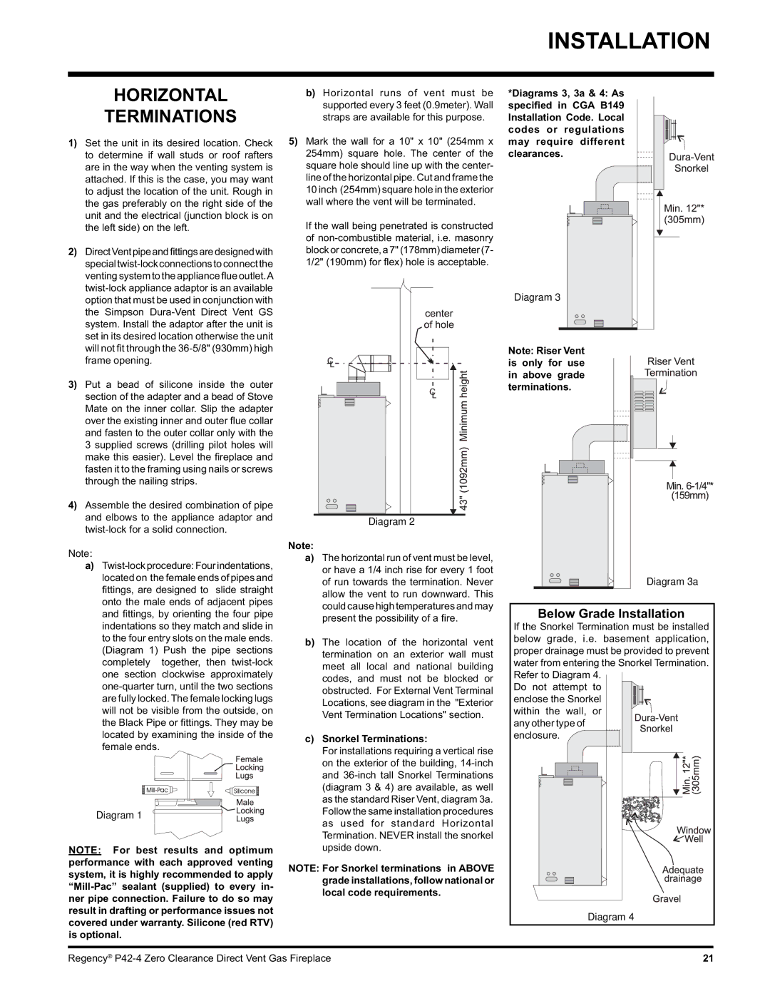
Installation flexibility is another advantage, with options for direct vent systems allowing for installation in various orientations and settings. This ensures homeowners can enjoy an attractive fireplace without needing extensive renovations or structural changes.
In conclusion, the Regency P42-LP4 and P42-NG4 are standout choices for anyone seeking a powerful, efficient, and stylish gas fireplace. With their innovative technologies, customizable features, and remarkable heating capabilities, these models offer an ideal focal point and cozy environment for any living space. They embody the perfect blend of modern design and traditional warmth, making them an excellent investment for enhancing home comfort and elegance.