INSTALLATION

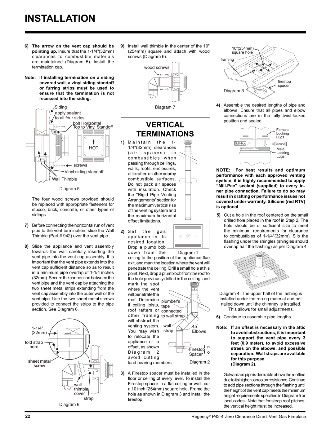
6)The arrow on the vent cap should be pointing up. Insure that the 1-1/4"(32mm) clearances to combustible materials are maintained (Diagram 5). Install the termination cap.

Note: If installing termination on a siding covered wall, a vinyl siding standoff or furring strips must be used to ensure that the termination is not recessed into the siding.

9) Install wall thimble in the center of the 10" (254mm) square and attach with wood screws (Diagram 6).

Diagram 3

Diagram 5

The four wood screws provided should be replaced with appropriate fasteners for stucco, brick, concrete, or other types of sidings.

7)Before connecting the horizontal run of vent pipe to the vent termination, slide the Wall Thimble (Part # 942) over the vent pipe.

8)Slide the appliance and vent assembly towards the wall carefully inserting the vent pipe into the vent cap assembly. It is important that the vent pipe extends into the vent cap sufficient distance so as to result in a minimum pipe overlap of 1-1/4 inches (32mm).Secure theconnectionbetweenthe vent pipe and the vent cap by attaching the two sheet metal strips extending from the vent cap assembly into the outer wall of the vent pipe. Use the two sheet metal screws provided to connect the strips to the pipe section. See Diagram 6.

Diagram 6

Diagram 7

VERTICAL

TERMINATIONS

1) M a i n t a i n

t h e

1-


1/4"(32mm) clearances


( a i r

s p a c e s )


t o


combustibles

when


passing through ceilings,


walls, roofs, enclosures,


atticrafter,orothernearby


combustible

surfaces.


Do not pack air spaces


with insulation. Check


the "Rigid Pipe Venting


Arrangements"sectionfor


the maximum vertical rise


of the venting system and


the maximum horizontal


offset limitations.


2) S e t

t h e

g a s


appliance

in

its


desired location.


Drop a plumb bob


down

from

the


Diagram 1

ceiling to the position of the appliance fl ue

exit,andmarkthelocationwheretheventwill

penetrate the ceiling. Drill a small hole at his

point. Next, drop a plumb bob from the roof to

the hole previously drilled in the ceiling, and

mark

the

spot


where

the

vent


willpenetratethe


roof. Determine


if ceiling joists,


roof rafters

or


other

framing


will obstruct the


venting system.


You may wish


to relocate

the


appliance or

to


offset, as shown


i n


D i a g r a m


2


t o

avoid

cutting


Diagram 2

load bearing members.


3)A Firestop spacer must be installed in the fl oor or ceiling of every level. To install the Firestop spacer in a fl at ceiling or wall, cut a 10 inch (254mm) square hole. Frame the hole as shown in Diagram 3 and install the fi restop.

4)Assemble the desired lengths of pipe and elbows. Ensure that all pipes and elbow connections are in the fully twist-locked position and sealed.

NOTE: For best results and optimum performance with each approved venting system, it is highly recommended to apply “Mill-Pac” sealant (supplied) to every in- ner pipe connection. Failure to do so may result in drafting or performance issues not covered under warranty. Silicone (red RTV) is optional.

5)Cut a hole in the roof centered on the small drilled hole placed in the roof in Step 2. The hole should be of sufficient size to meet the minimum requirements for clearance to combustibles of 1-1/4"(32mm). Slip the fl ashing under the shingles (shingles should overlap half the fl ashing) as per Diagram 4.

Diagram 4: The upper half of the fl ashing is installed under the roofi ng material and not nailed down until the chimney is installed.

This allows for small adjustments.

6)Continue to assemble pipe lengths.

Note: If an offset is necessary in the attic to avoid obstructions, it is important to support the vent pipe every 3 feet (0.9 meter), to avoid excessive stress on the elbows, and possible separation. Wall straps are available for this purpose

(Diagram 2).

Galvanizedpipeisdesirableabovetheroofline duetoitshighercorrosionresistance.Continue to add pipe sections through the flashing until the height of the vent cap meets the minimum height requirements specified in Diagram 5 or local codes. Note that for steep roof pitches, the vertical height must be increased.

22

Regency® P42-4 Zero Clearance Direct Vent Gas Fireplace

Page 22
Image 22
Regency P42-NG4, P42-LP4 installation manual Vertical Terminations, Diagram

P42-LP4, P42-NG4 specifications

The Regency P42-LP4 and P42-NG4 are two exceptional gas fireplace models that beautifully combine functionality and aesthetic appeal, making them ideal for various home settings. Built with durability and efficiency in mind, these models are equipped with advanced features that enhance user experience.

One of the main highlights of the P42 series is its impressive heating capacity. Both the P42-LP4 and P42-NG4 are designed to deliver substantial warmth, ensuring that spaces of different sizes can be comfortably heated. With a maximum input of up to 40,000 BTUs, these units can effectively warm large living areas, making them perfect for modern homes.

In terms of design, the P42 models boast a sleek and contemporary look. They feature a large viewing area that allows for an expansive flame presentation, inviting warmth and ambiance into your home. The optional polished or brushed stainless steel front and various media options, including glass rocks or logs, provide customization, allowing homeowners to tailor the look of their fireplace to match their personal style and existing decor.

The technologies integrated into the Regency P42-LP4 and P42-NG4 are notable. Both models come equipped with system safety features, ensuring peace of mind. Additionally, they support the use of a programmable remote control, making adjustments to the temperature and flame appearance effortless while allowing homeowners to maintain comfort with just a click.

Efficiency is another key characteristic. These gas fireplaces highlight energy efficiency, designed to maximize heat output while minimizing fuel consumption. They have received high-efficiency ratings, which may qualify users for rebates or incentives in many regions, aligning with the growing demand for eco-friendly home heating solutions.

Installation flexibility is another advantage, with options for direct vent systems allowing for installation in various orientations and settings. This ensures homeowners can enjoy an attractive fireplace without needing extensive renovations or structural changes.

In conclusion, the Regency P42-LP4 and P42-NG4 are standout choices for anyone seeking a powerful, efficient, and stylish gas fireplace. With their innovative technologies, customizable features, and remarkable heating capabilities, these models offer an ideal focal point and cozy environment for any living space. They embody the perfect blend of modern design and traditional warmth, making them an excellent investment for enhancing home comfort and elegance.