INSTALLATION

HORIZONTAL

TERMINATIONS

Install the flue system according to the manufacturer's instructions included with the components.

1)Set the unit in its desired location. Check to determine if wall studs or roof rafters are in the way when the fl ueing system is attached. If this is the case, you may want to adjust the location of the unit. Rough in the gas preferably on the right side of the unit and the electrical (junction block is on the left side) on the left.

2)Co Axial Flue pipe and fi ttings are designed with special twist-lock connections to connect the fl ueing system to the appliance fl ue outlet. A twist-lock appliance adaptor is an available option that must be used in conjunction with the Simpson Dura-Vent Co Axial Flue GS system.

3)Put a bead of silicone inside the outer section of the adapter and a bead of Stove Mate on the inner collar. Slip the adapter over the existing inner and outer fl ue collar and fasten to the outer collar only with the 3 supplied screws (drilling pilot holes will make this easier). Level the fi replace and fasten it to the framing using nails or screws through the nailing strips.

4)Assemble the desired combination of pipe and elbows to the appliance adaptor and twist-lock for a solid connection.

Note:

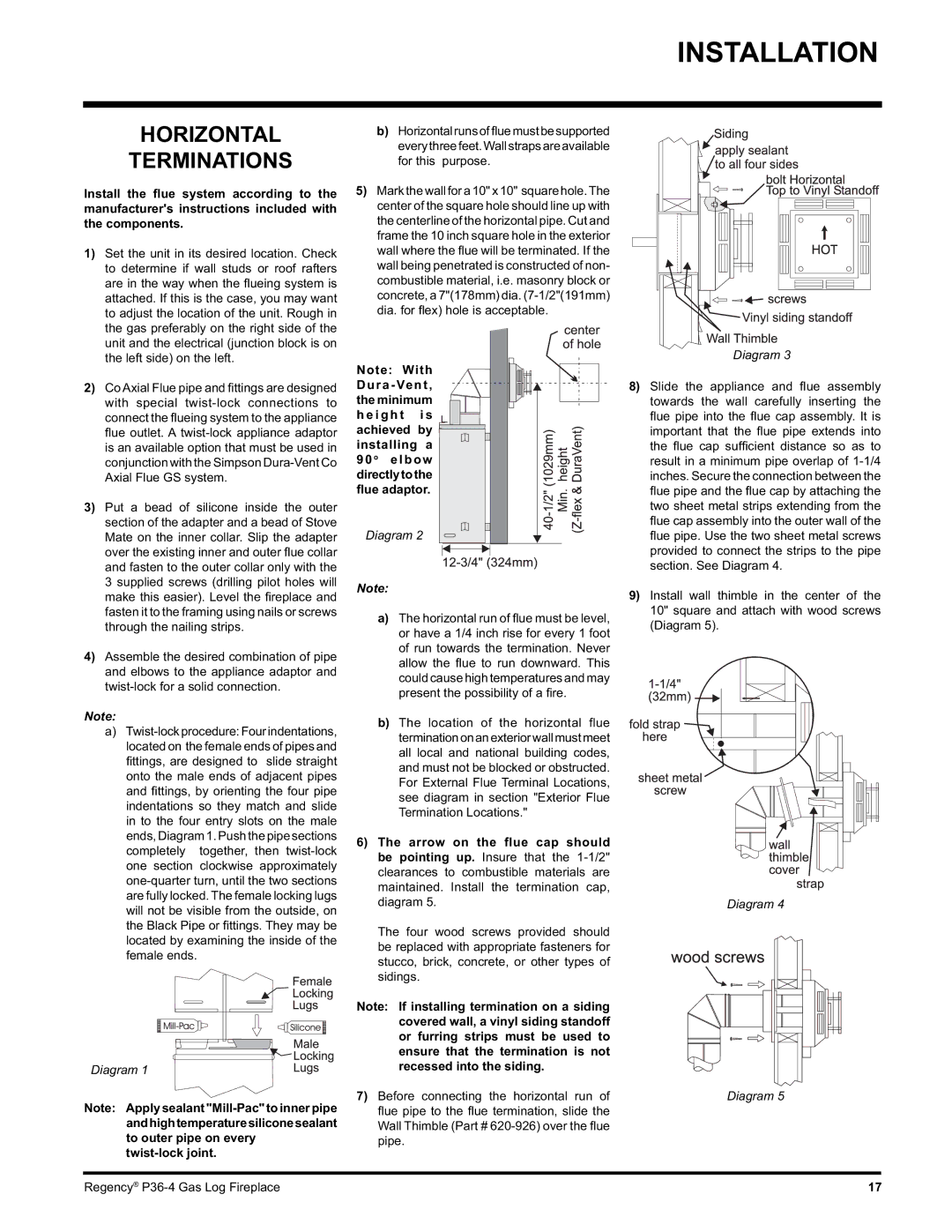
a)Twist-lockprocedure:Fourindentations, located on the female ends of pipes and fi ttings, are designed to slide straight onto the male ends of adjacent pipes and fi ttings, by orienting the four pipe indentations so they match and slide in to the four entry slots on the male ends, Diagram 1. Push the pipe sections completely together, then twist-lock one section clockwise approximately one-quarter turn, until the two sections are fully locked. The female locking lugs will not be visible from the outside, on the Black Pipe or fi ttings. They may be located by examining the inside of the female ends.

Diagram 1

Note: Apply sealant "Mill-Pac" to inner pipe andhightemperaturesiliconesealant to outer pipe on every twist-lock joint.

b)Horizontalrunsoffluemustbesupported everythreefeet.Wallstrapsareavailable for this purpose.

5)Mark the wall for a 10" x 10" square hole.The center of the square hole should line up with the centerline of the horizontal pipe. Cut and frame the 10 inch square hole in the exterior wall where the fl ue will be terminated. If the wall being penetrated is constructed of non- combustible material, i.e. masonry block or concrete, a 7"(178mm) dia. (7-1/2"(191mm) dia. for fl ex) hole is acceptable.

Note: With

Dura-Vent,

the minimum h e i g h t i s

achieved by installing a 90 o elbow

directlytothe flue adaptor.

Diagram 2

Note:

a)The horizontal run of fl ue must be level, or have a 1/4 inch rise for every 1 foot of run towards the termination. Never allow the fl ue to run downward. This could cause high temperatures and may present the possibility of a fi re.

b)The location of the horizontal flue terminationonanexteriorwallmustmeet all local and national building codes, and must not be blocked or obstructed. For External Flue Terminal Locations, see diagram in section "Exterior Flue Termination Locations."

6)The arrow on the flue cap should be pointing up. Insure that the 1-1/2" clearances to combustible materials are maintained. Install the termination cap, diagram 5.

The four wood screws provided should be replaced with appropriate fasteners for stucco, brick, concrete, or other types of sidings.

Note: If installing termination on a siding covered wall, a vinyl siding standoff or furring strips must be used to ensure that the termination is not recessed into the siding.

7)Before connecting the horizontal run of fl ue pipe to the fl ue termination, slide the Wall Thimble (Part # 620-926) over the fl ue pipe.

Diagram 3

8)Slide the appliance and fl ue assembly

towards the wall carefully inserting the

ue pipe into the fl ue cap assembly. It is important that the fl ue pipe extends into the fl ue cap suffi cient distance so as to result in a minimum pipe overlap of 1-1/4 inches. Secure the connection between the

ue pipe and the fl ue cap by attaching the two sheet metal strips extending from the

ue cap assembly into the outer wall of the

ue pipe. Use the two sheet metal screws provided to connect the strips to the pipe section. See Diagram 4.

9)Install wall thimble in the center of the 10" square and attach with wood screws (Diagram 5).

Diagram 4

Diagram 5

Regency® P36-4 Gas Log Fireplace

17

Page 17
Image 17
Regency Wraps P36-NG4, P36-LPG4 manual Horizontal Terminations, Dura-Vent

P36-NG4, P36-LPG4 specifications

Regency Wraps has made a significant mark in the world of grill accessories with its high-quality products, particularly the P36-LPG4 and P36-NG4 wraps. These wraps are designed specifically for grill enthusiasts who value durability, functionality, and aesthetic appeal in their cooking equipment.

The P36-LPG4 model is tailored for those who prefer liquid propane as their fuel source. It boasts a robust construction that ensures longevity and resilience against the elements. One of the key features of the P36-LPG4 is its heat-resistant fabric, which is crafted to withstand high temperatures without compromising the integrity of the wrap. This makes it an ideal choice for situations where intense heat is a norm, providing both safety and performance.

On the other hand, the P36-NG4 model caters to natural gas users. Similar to its LPG counterpart, the P36-NG4 is engineered to handle the rigors of outdoor grilling while offering a stylish appearance. The wrap is designed to fit a range of traditional grills, ensuring a snug yet flexible fit that protects the grill from dust, debris, and harsh weather conditions.

Both models feature advanced technologies, including UV resistance, which helps in maintaining the vibrant colors and quality of the fabric over time. This is crucial for outdoor gear that often faces prolonged exposure to the sun, preserving the product's aesthetic charm as well as its functional attributes.

The characteristics of the P36-LPG4 and P36-NG4 wraps extend beyond mere protection. They are equipped with user-friendly features such as easy installation; most users can simply slip the wrap over their grill in seconds. The wraps are also lightweight, which enhances portability for grillers who like to take their equipment on the go.

Furthermore, both wraps are designed with ease of maintenance in mind. They can be cleaned effortlessly, ensuring that grill enthusiasts can maintain their equipment in pristine condition without excessive effort or time.

In summary, Regency Wraps offers the P36-LPG4 and P36-NG4 models as the ultimate solution for grill protection, combining style with superior functionality. With their durable construction, advanced technologies, and user-friendly design, these wraps are a worthy investment for any grilling aficionado looking to enhance their outdoor cooking experience.