INSTALLATION

VERTICAL

TERMINATIONS

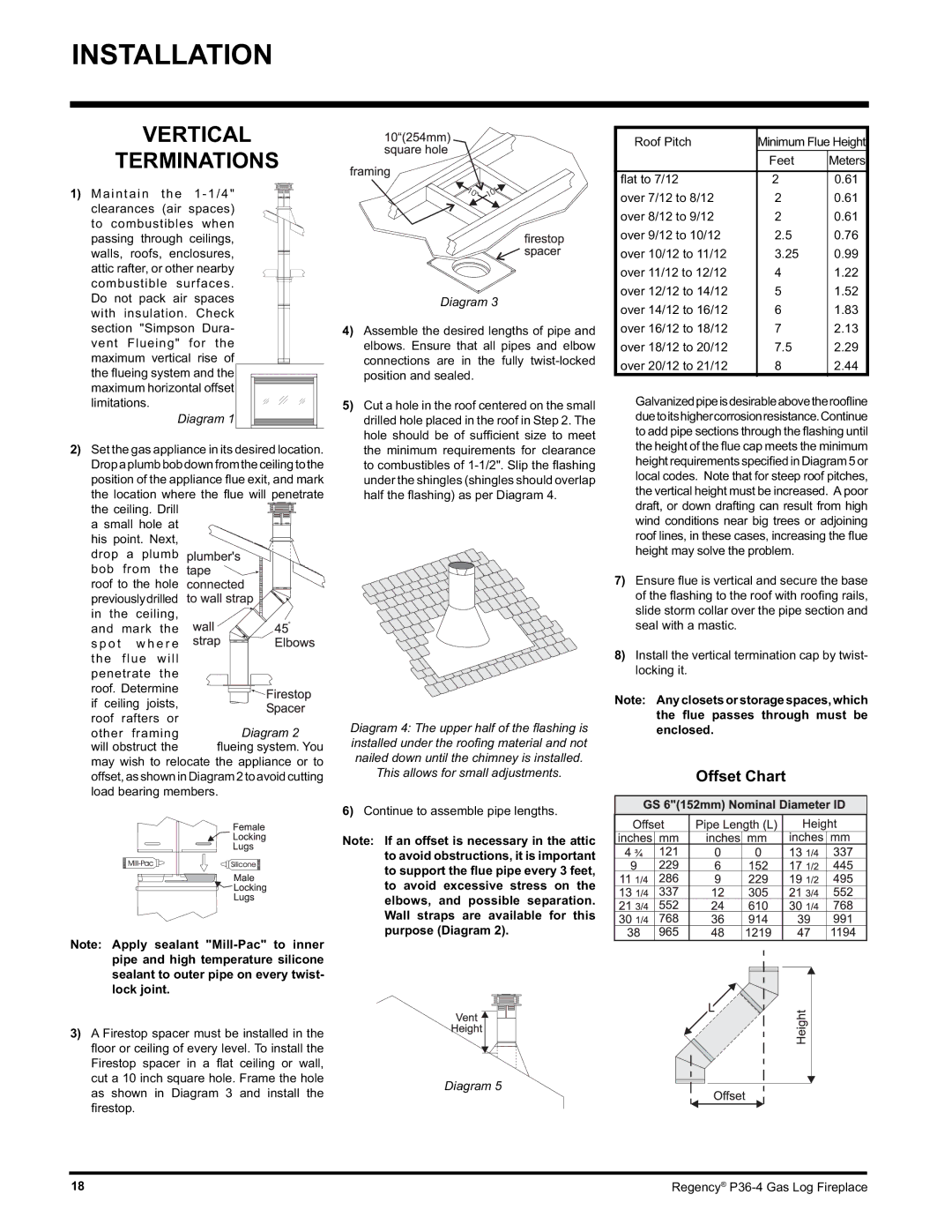
1) Maintain the 1-1/4" clearances (air spaces) to combustibles when passing through ceilings, walls, roofs, enclosures, attic rafter, or other nearby combustible surfaces. Do not pack air spaces with insulation. Check section "Simpson Dura- vent Flueing" for the maximum vertical rise of the fl ueing system and the maximum horizontal offset limitations.

Diagram 1

2)Set the gas appliance in its desired location.

Dropaplumbbobdownfromtheceilingtothe position of the appliance fl ue exit, and mark the location where the fl ue will penetrate

the ceiling. Drill


a small hole at


his point. Next,


drop

a plumb


bob

from

the


roof to the hole


previouslydrilled


in the ceiling,


and

mark

the


s p o t

w h e r e


the

flue

will


penetrate

the


roof. Determine


if ceiling joists,


roof

rafters or

Diagram 2

other framing

will obstruct the

fl ueing system. You

may wish to relocate the appliance or to offset,asshowninDiagram2toavoidcutting load bearing members.

Note: Apply sealant "Mill-Pac" to inner pipe and high temperature silicone sealant to outer pipe on every twist- lock joint.

3)A Firestop spacer must be installed in the

oor or ceiling of every level. To install the Firestop spacer in a fl at ceiling or wall, cut a 10 inch square hole. Frame the hole

as shown in Diagram 3 and install the fi restop.

Diagram 3

4)Assemble the desired lengths of pipe and elbows. Ensure that all pipes and elbow connections are in the fully twist-locked position and sealed.

5)Cut a hole in the roof centered on the small drilled hole placed in the roof in Step 2. The hole should be of suffi cient size to meet the minimum requirements for clearance to combustibles of 1-1/2". Slip the fl ashing under the shingles (shingles should overlap half the fl ashing) as per Diagram 4.

Diagram 4: The upper half of the fl ashing is installed under the roofi ng material and not nailed down until the chimney is installed.

This allows for small adjustments.

6)Continue to assemble pipe lengths.

Note: If an offset is necessary in the attic to avoid obstructions, it is important to support the flue pipe every 3 feet, to avoid excessive stress on the elbows, and possible separation. Wall straps are available for this purpose (Diagram 2).

Diagram 5

Roof Pitch

Minimum Flue Height


Feet

Meters


fl at to 7/12

2

0.61

over 7/12 to 8/12

2

0.61

over 8/12 to 9/12

2

0.61

over 9/12 to 10/12

2.5

0.76

over 10/12 to 11/12

3.25

0.99

over 11/12 to 12/12

4

1.22

over 12/12 to 14/12

5

1.52

over 14/12 to 16/12

6

1.83

over 16/12 to 18/12

7

2.13

over 18/12 to 20/12

7.5

2.29

over 20/12 to 21/12

8

2.44

Galvanizedpipeisdesirableabovetheroofline duetoitshighercorrosionresistance.Continue to add pipe sections through the flashing until the height of the flue cap meets the minimum height requirements specified in Diagram 5 or local codes. Note that for steep roof pitches, the vertical height must be increased. A poor draft, or down drafting can result from high wind conditions near big trees or adjoining roof lines, in these cases, increasing the flue height may solve the problem.

7)Ensure fl ue is vertical and secure the base of the fl ashing to the roof with roofi ng rails, slide storm collar over the pipe section and seal with a mastic.

8)Install the vertical termination cap by twist- locking it.

Note: Any closets or storage spaces, which the flue passes through must be enclosed.

Offset Chart

18

Regency® P36-4 Gas Log Fireplace

Page 18
Image 18
Regency Wraps P36-LPG4, P36-NG4 manual Vertical Terminations, Offset Chart, This allows for small adjustments

P36-NG4, P36-LPG4 specifications

Regency Wraps has made a significant mark in the world of grill accessories with its high-quality products, particularly the P36-LPG4 and P36-NG4 wraps. These wraps are designed specifically for grill enthusiasts who value durability, functionality, and aesthetic appeal in their cooking equipment.

The P36-LPG4 model is tailored for those who prefer liquid propane as their fuel source. It boasts a robust construction that ensures longevity and resilience against the elements. One of the key features of the P36-LPG4 is its heat-resistant fabric, which is crafted to withstand high temperatures without compromising the integrity of the wrap. This makes it an ideal choice for situations where intense heat is a norm, providing both safety and performance.

On the other hand, the P36-NG4 model caters to natural gas users. Similar to its LPG counterpart, the P36-NG4 is engineered to handle the rigors of outdoor grilling while offering a stylish appearance. The wrap is designed to fit a range of traditional grills, ensuring a snug yet flexible fit that protects the grill from dust, debris, and harsh weather conditions.

Both models feature advanced technologies, including UV resistance, which helps in maintaining the vibrant colors and quality of the fabric over time. This is crucial for outdoor gear that often faces prolonged exposure to the sun, preserving the product's aesthetic charm as well as its functional attributes.

The characteristics of the P36-LPG4 and P36-NG4 wraps extend beyond mere protection. They are equipped with user-friendly features such as easy installation; most users can simply slip the wrap over their grill in seconds. The wraps are also lightweight, which enhances portability for grillers who like to take their equipment on the go.

Furthermore, both wraps are designed with ease of maintenance in mind. They can be cleaned effortlessly, ensuring that grill enthusiasts can maintain their equipment in pristine condition without excessive effort or time.

In summary, Regency Wraps offers the P36-LPG4 and P36-NG4 models as the ultimate solution for grill protection, combining style with superior functionality. With their durable construction, advanced technologies, and user-friendly design, these wraps are a worthy investment for any grilling aficionado looking to enhance their outdoor cooking experience.