REMINGTON QFP40 Direct Vent FIREPLACE
VERTICAL INSTALLATION INSTRUCTIONS (CONT.)
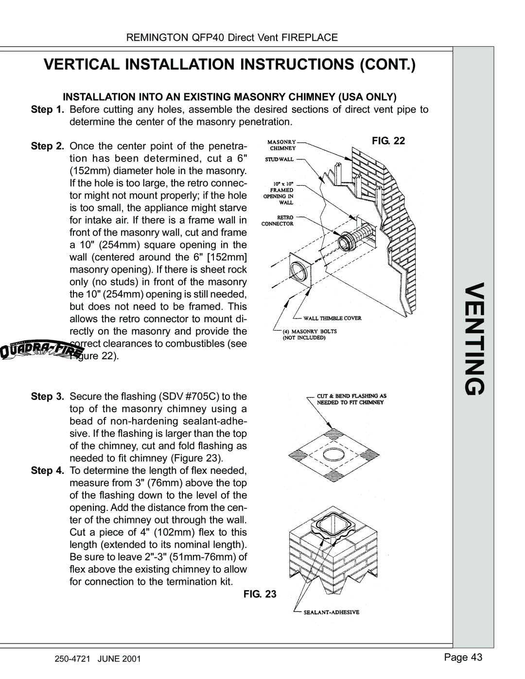
INSTALLATION INTO AN EXISTING MASONRY CHIMNEY (USA ONLY)
Step 1. Before cutting any holes, assemble the desired sections of direct vent pipe to determine the center of the masonry penetration.
Step 2. Once the center point of the penetra- | FIG. 22 |
| |
tion has been determined, cut a 6" |
|
(152mm) diameter hole in the masonry. |
|
If the hole is too large, the retro connec- |
|
tor might not mount properly; if the hole |
|
is too small, the appliance might starve |
|
for intake air. If there is a frame wall in |
|
front of the masonry wall, cut and frame |
|
a 10" (254mm) square opening in the |
|
wall (centered around the 6" [152mm] |
|
masonry opening). If there is sheet rock |
|
only (no studs) in front of the masonry |
|
the 10" (254mm) opening is still needed, |
|
but does not need to be framed. This |
|
allows the retro connector to mount di- |
|
rectly on the masonry and provide the |
|
correct clearances to combustibles (see |
|
Figure 22). |
|
Step 3. Secure the flashing (SDV #705C) to the top of the masonry chimney using a bead of
Step 4. To determine the length of flex needed, measure from 3" (76mm) above the top of the flashing down to the level of the opening. Add the distance from the cen- ter of the chimney out through the wall. Cut a piece of 4" (102mm) flex to this length (extended to its nominal length). Be sure to leave
FIG. 23
VENTING
Page 43 |