Alignment (Adjustments)
WARNING: To reduce the risk of injury from unexpected starting or electrical shock, do not plug the saw in. The power cord must remain unplugged whenever you are working on the saw.
NOTE: For best results, the saw must be properaly aligned before mounting and using the laser system.
Step One: Repositioning Zero Clear- ance Blade Insert
The zero clearance blade insert needs to be repositioned so it is temporarily out of the way when aligning the blade. It may be replaced after the blade is aligned.
1.Loosen the three screws that secure the zero clearance blade insert on one side of the blade.
2.Slide the zero clearance insert away from the blade as far as possible.
3.Retighten the three screws.
4.Repeat steps
Step Two: Slide Tube Adjustment
1.Place the powerhead in the 0° miter/0° bevel index and lock head in lower posi- tion.
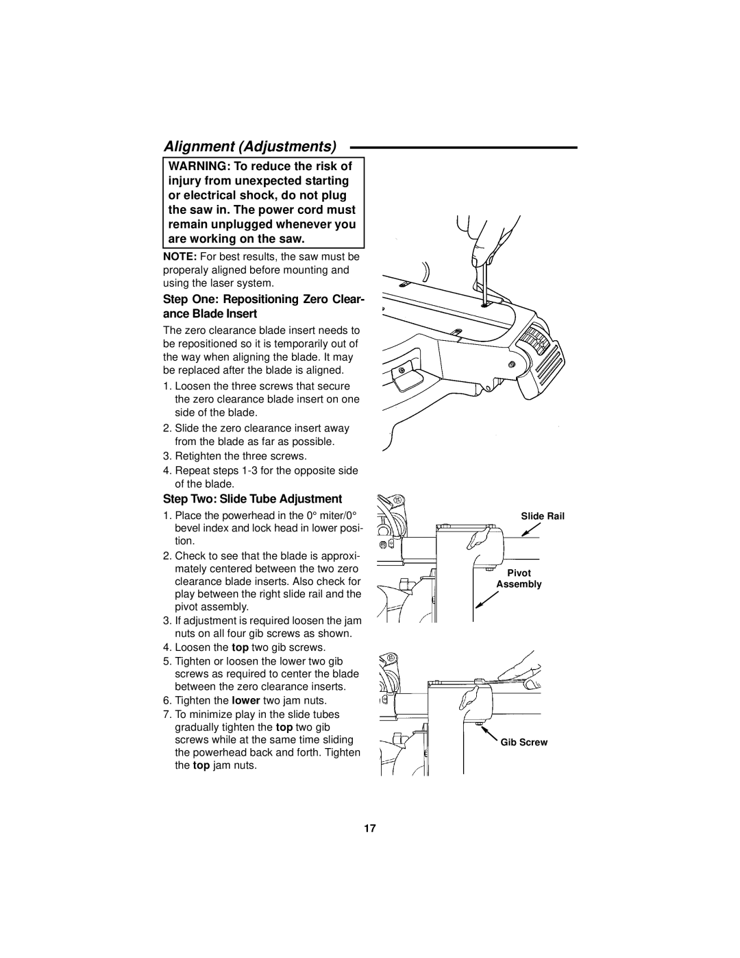
2.Check to see that the blade is approxi- mately centered between the two zero clearance blade inserts. Also check for play between the right slide rail and the pivot assembly.
3.If adjustment is required loosen the jam nuts on all four gib screws as shown.
4.Loosen the top two gib screws.
5.Tighten or loosen the lower two gib screws as required to center the blade between the zero clearance inserts.
6.Tighten the lower two jam nuts.
7.To minimize play in the slide tubes gradually tighten the top two gib screws while at the same time sliding the powerhead back and forth. Tighten the top jam nuts.
Slide Rail
Pivot
Assembly
Gib Screw
17