Step Four: Blade Square to Table (Bevel Adjustment)
1.Place the saw in the 0° bevel index position and make sure bevel lock is disengaged.
2.Lower the blade and engage the head hold down.
3.Use a combination square to check that the blade is 90° to the table. If the blade does not contact the full length of the square:
a.Lift the bevel lock lever.
b.Loosen the two socket head screws that secure the bevel scale.
c.Grasp the upper metal guard and move the powerhead left or right until the blade makes full contact with the length of the square.
d.Securely tighten two socket head screws.
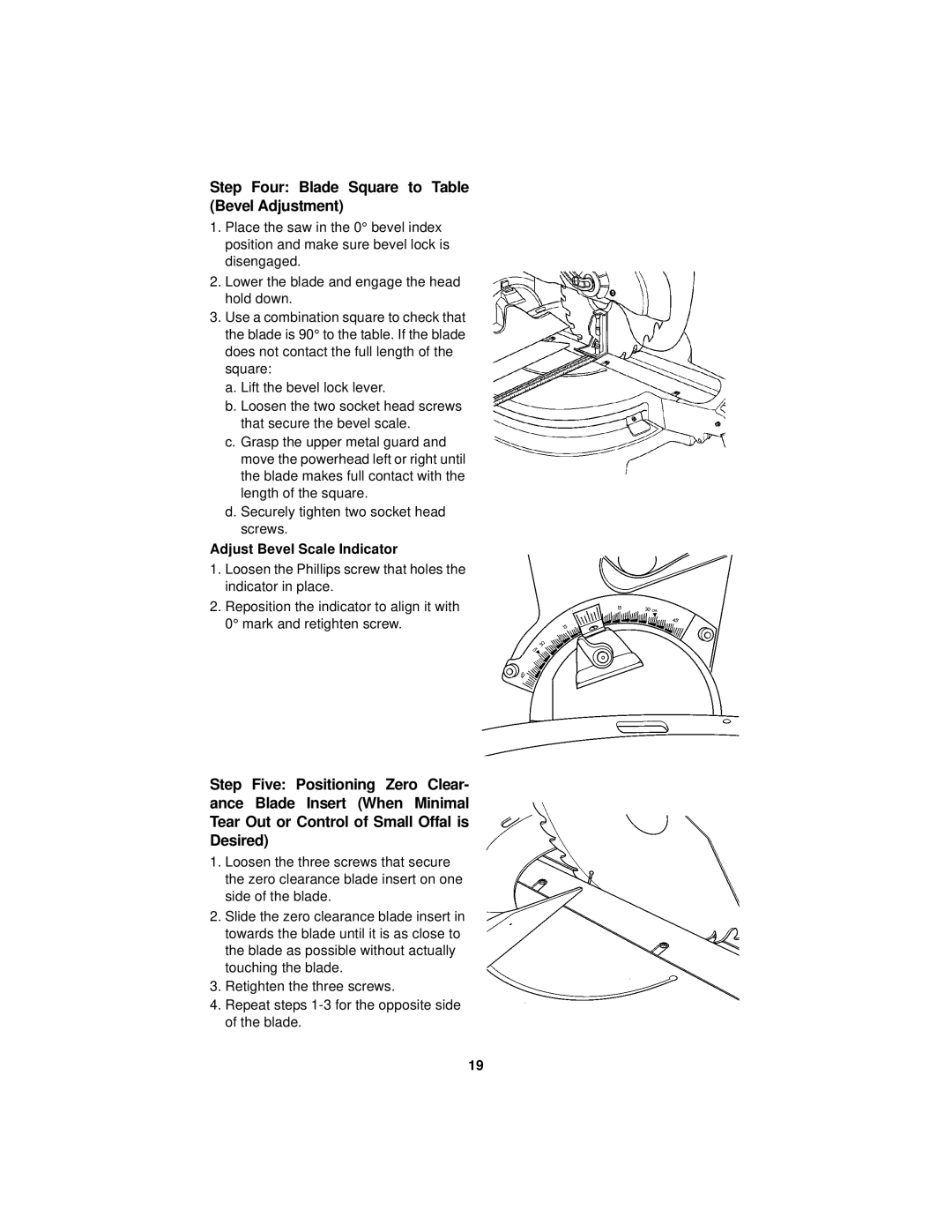
Adjust Bevel Scale Indicator
1.Loosen the Phillips screw that holes the indicator in place.
2.Reposition the indicator to align it with 0° mark and retighten screw.
Step Five: Positioning Zero Clear- ance Blade Insert (When Minimal Tear Out or Control of Small Offal is Desired)
1.Loosen the three screws that secure the zero clearance blade insert on one side of the blade.
2.Slide the zero clearance blade insert in towards the blade until it is as close to the blade as possible without actually touching the blade.
3.Retighten the three screws.
4.Repeat steps
19