SECTION 15: SERVICING INSTRUCTIONS
SECTION 15: SERVICING INSTRUCTIONS
DANGER |
| WARNING |
| |
Electrical Shock Hazard | Explosion Hazard | Burn Hazard | Cut/Pinch Hazard | |
Disconnect electric | Turn off gas supply to | Allow heater to cool | Wear protective gear | |
heater before service. | before service. | during installation, | ||
before service. | ||||
|
| operation and service. | ||
|
| Tubing may still be hot | ||
More than one |
| Edges are sharp. | ||
disconnect switch may |
| after operation. | ||
be required to |
|
|
| |
disconnect electric from |
|
|
| |
heater. |
|
|
| |
Heater must be |
|
|
| |
connected to a properly |
|
|
| |
grounded electrical |
|
|
| |
source. |
|
|
|
Failure to follow these instructions can result in death, electric shock, injury or property damage.
IMPORTANT: Never use the heater as a support for ladders or other access equipment. Always test for gas soundness with a suitable detection fluid after completing any servicing or exchange of gas carrying component. On completion of any service/fault finding tasks which require the breaking and remaking of electrical connections, the checks:- A:Earth Continuity, B:Polarity and C:Resistance to Earth must then be repeated.
order. Carry out the Testing Procedure. See Page 59, Section 14.2.
15.2 Component Removal
First, isolate the heater from the gas and electrical supplies. Entry to the burner assembly is gained by removing the door screws and opening the hinged side cover. Entry to the combustion chamber is gained by removing the combustion chamber cover.
15.1 Annual Procedure
Carry out the following procedure annually. The preferred time would be immediately before the winter heating period. If very dirty conditions arise, it may be necessary to carry out this procedure more often. If the unit takes in air through an air duct or filter assembly, more frequent service may be necessary.
15.1.1 Burner and Fan Removal
Isolate the heater from the gas and electrical supplies. Remove the fan plug from the burner. Unscrew the securing screws on the burner flange. The burner can now be removed. Take care not to disturb the gasket on the flanged burner tube. Unscrew the securing screw on the fan flange spigot. The fan can now be removed.
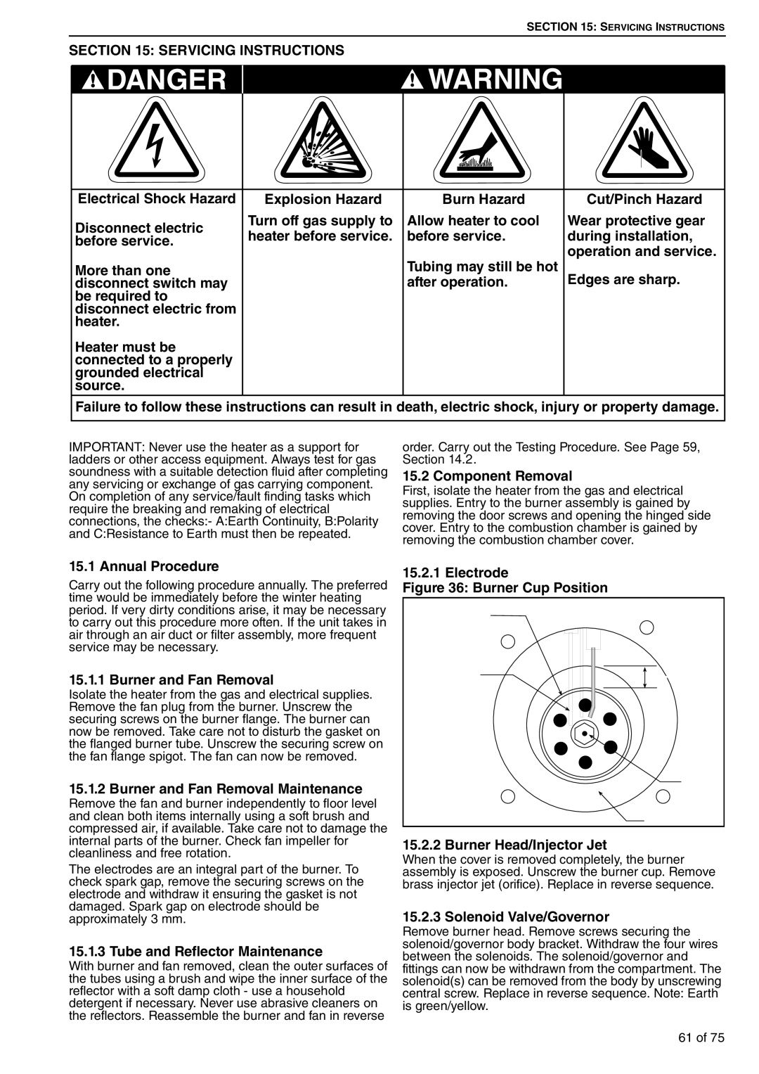
15.2.1 Electrode
Figure 36: Burner Cup Position
15.1.2Burner and Fan Removal Maintenance
Remove the fan and burner independently to floor level and clean both items internally using a soft brush and compressed air, if available. Take care not to damage the internal parts of the burner. Check fan impeller for cleanliness and free rotation.
The electrodes are an integral part of the burner. To check spark gap, remove the securing screws on the electrode and withdraw it ensuring the gasket is not damaged. Spark gap on electrode should be approximately 3 mm.
15.1.3 Tube and Reflector Maintenance
With burner and fan removed, clean the outer surfaces of the tubes using a brush and wipe the inner surface of the reflector with a soft damp cloth - use a household detergent if necessary. Never use abrasive cleaners on the reflectors. Reassemble the burner and fan in reverse
15.2.2 Burner Head/Injector Jet
When the cover is removed completely, the burner assembly is exposed. Unscrew the burner cup. Remove brass injector jet (orifice). Replace in reverse sequence.
15.2.3 Solenoid Valve/Governor
Remove burner head. Remove screws securing the solenoid/governor body bracket. Withdraw the four wires between the solenoids. The solenoid/governor and fittings can now be withdrawn from the compartment. The solenoid(s) can be removed from the body by unscrewing central screw. Replace in reverse sequence. Note: Earth is green/yellow.
61 of 75