SECTION 18: SPECIFICATIONS
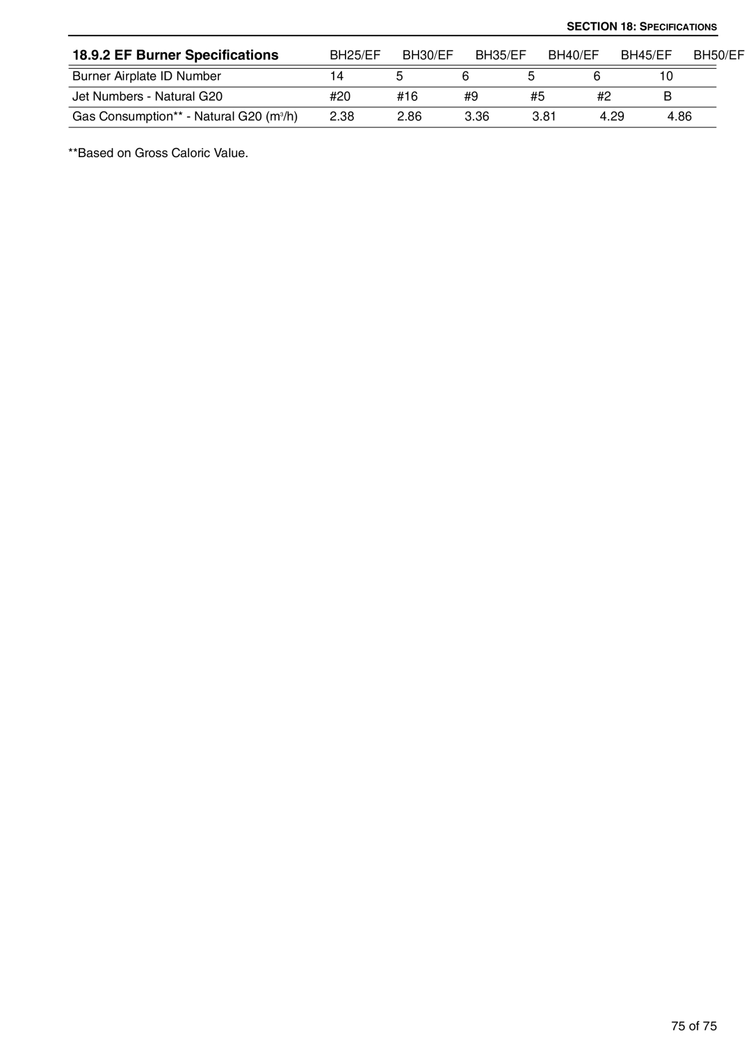
18.9.2 EF Burner Specifications | BH25/EF | BH30/EF | BH35/EF | BH40/EF | BH45/EF | BH50/EF |
|
|
|
|
|
|
|
Burner Airplate ID Number | 14 | 5 | 6 | 5 | 6 | 10 |
|
|
|
|
|
|
|
Jet Numbers - Natural G20 | #20 | #16 | #9 | #5 | #2 | B |
|
|
|
|
|
|
|
Gas Consumption** - Natural G20 (m3/h) | 2.38 | 2.86 | 3.36 | 3.81 | 4.29 | 4.86 |
|
|
|
|
|
|
|
**Based on Gross Caloric Value.
75 of 75