SECTION 18: SPECIFICATIONS
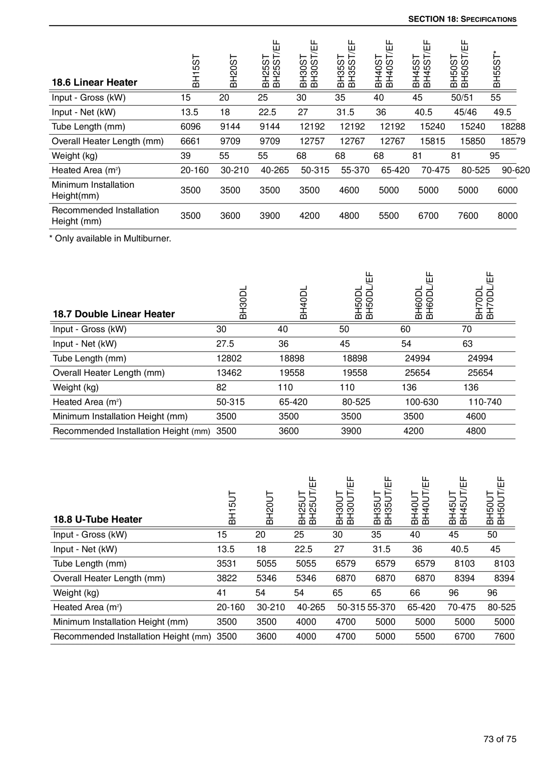
18.6 Linear Heater
BH15ST | BH20ST | BH25ST | BH25ST/EF | BH30ST | BH30ST/EF | BH35ST | BH35ST/EF | BH40ST | BH40ST/EF | BH45ST | BH45ST/EF | BH50ST | BH50ST/EF | BH55ST* |
Input - Gross (kW) | 15 | 20 | 25 | 30 | 35 | 40 | 45 | 50/51 | 55 | |
Input - Net (kW) | 13.5 | 18 | 22.5 | 27 | 31.5 | 36 | 40.5 | 45/46 | 49.5 | |
|
|
|
|
|
|
|
|
|
| |
Tube Length (mm) | 6096 | 9144 | 9144 | 12192 | 12192 | 12192 | 15240 | 15240 | 18288 | |
|
|
|
|
|
|
|
|
|
| |
Overall Heater Length (mm) | 6661 | 9709 | 9709 | 12757 | 12767 | 12767 | 15815 | 15850 | 18579 | |
|
|
|
|
|
|
|
|
|
| |
Weight (kg) | 39 | 55 | 55 | 68 | 68 | 68 | 81 | 81 | 95 | |
|
|
|
|
|
|
|
|
|
| |
Heated Area (m2) | ||||||||||
|
|
|
|
|
|
|
|
|
| |
Minimum Installation | 3500 | 3500 | 3500 | 3500 | 4600 | 5000 | 5000 | 5000 | 6000 | |
Height(mm) | ||||||||||
|
|
|
|
|
|
|
|
| ||
|
|
|
|
|
|
|
|
|
| |
Recommended Installation | 3500 | 3600 | 3900 | 4200 | 4800 | 5500 | 6700 | 7600 | 8000 | |
Height (mm) | ||||||||||
|
|
|
|
|
|
|
|
| ||
|
|
|
|
|
|
|
|
|
|
* Only available in Multiburner.
18.7 Double Linear Heater
BH30DL | BH40DL | BH50DL | BH50DL/EF | BH60DL | BH60DL/EF | BH70DL | BH70DL/EF |
Input - Gross (kW) | 30 | 40 | 50 | 60 | 70 |
Input - Net (kW) | 27.5 | 36 | 45 | 54 | 63 |
|
|
|
|
|
|
Tube Length (mm) | 12802 | 18898 | 18898 | 24994 | 24994 |
|
|
|
|
|
|
Overall Heater Length (mm) | 13462 | 19558 | 19558 | 25654 | 25654 |
|
|
|
|
|
|
Weight (kg) | 82 | 110 | 110 | 136 | 136 |
|
|
|
|
|
|
Heated Area (m2) | |||||
|
|
|
|
|
|
Minimum Installation Height (mm) | 3500 | 3500 | 3500 | 3500 | 4600 |
|
|
|
|
|
|
Recommended Installation Height (mm) | 3500 | 3600 | 3900 | 4200 | 4800 |
|
|
|
|
|
|
18.8 U-Tube Heater
BH15UT | BH20UT | BH25UT | BH25UT/EF | BH30UT | BH30UT/EF | BH35UT | BH35UT/EF | BH40UT | BH40UT/EF | BH45UT | BH45UT/EF | BH50UT | BH50UT/EF |
Input - Gross (kW) | 15 | 20 | 25 | 30 | 35 | 40 | 45 | 50 |
Input - Net (kW) | 13.5 | 18 | 22.5 | 27 | 31.5 | 36 | 40.5 | 45 |
|
|
|
|
|
|
|
|
|
Tube Length (mm) | 3531 | 5055 | 5055 | 6579 | 6579 | 6579 | 8103 | 8103 |
|
|
|
|
|
|
|
|
|
Overall Heater Length (mm) | 3822 | 5346 | 5346 | 6870 | 6870 | 6870 | 8394 | 8394 |
|
|
|
|
|
|
|
|
|
Weight (kg) | 41 | 54 | 54 | 65 | 65 | 66 | 96 | 96 |
|
|
|
|
|
|
|
|
|
Heated Area (m2) | ||||||||
|
|
|
|
|
|
|
|
|
Minimum Installation Height (mm) | 3500 | 3500 | 4000 | 4700 | 5000 | 5000 | 5000 | 5000 |
|
|
|
|
|
|
|
|
|
Recommended Installation Height (mm) | 3500 | 3600 | 4000 | 4700 | 5000 | 5500 | 6700 | 7600 |
|
|
|
|
|
|
|
|
|
73 of 75