Installation
1.Remove the two Yaw/X Adjustment Levers (item #8) from the bottom of the Anamorphic Lens Holder (item #5).
2.Place the Anamorphic Lens Holder on top of the AutoScope Carriage Plate or fixed CineWide base plate (item #7). Position the bracket so that the long slot at the bottom of the lens holder is perpendicular to the corresponding slots on the carriage plate or base plate.
3.Secure the Anamorphic Lens Holder to the plate using the Hex Bolts/Washers (item #6) and Yaw/X Adjustment Levers that you removed in Step 1.
4.Use the Lens Mounting Screws to attach the Lens Adapter Ring (item #1) to the Pitch Adjustment Yoke (item #2); see Figure
5.Use the Height/Y Adjustment
(item #4) and
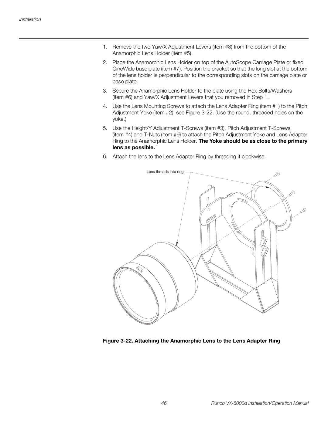
6.Attach the lens to the Lens Adapter Ring by threading it clockwise.
Lens threads into ring
SUCO![]()
F
Figure 3-22. Attaching the Anamorphic Lens to the Lens Adapter Ring
46 | Runco |