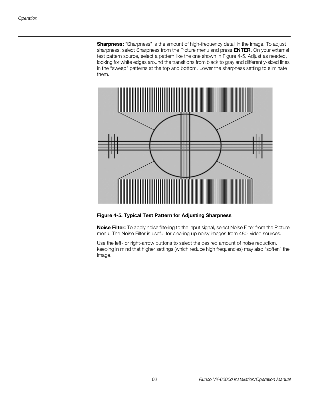
VX-6000d VX-6000d/CineWide VX-6000d/CineWide with AutoScope
VX-6000d
I N S T A L L A T I O N / O P E R A T I O N M A N U A L
1080p Digital Light ProcessingTM Projector
Page
RuncoCare Standard Two Year Limited Warranty
RuncoCare Standard Features
Warranty Coverage
Length of Warranty
RuncoCare Claim Procedure
Warranty Exclusions
Online Product Registration
Extended Service Options
Limitation of Implied Warranties
Effect of Local Law
Exclusion of Damages
COPYRIGHT AND TRADEMARKS
Important Safety Instructions
Compliance Information
DECLARATION OF CONFORMITY
FCC PART
INDUSTRY CANADA ICES-003
PRODUCT DISPOSAL
IMPORTANT RECYCLE INSTRUCTIONS
Runco VX-6000d Installation/Operation Manual
Table of Contents
RuncoCare Standard Two Year Limited Warranty
viii
Runco VX-6000d Installation/Operation Manual
Installing the Fixed CineWide Base Plate VX-6000d/CineWide
Maintenance and Troubleshooting
Specifications
Runco VX-6000d Installation/Operation Manual
Operation
Table of Contents
Runco VX-6000d Installation/Operation Manual
List of Figures
4-5. Typical Test Pattern for Adjusting Sharpness
CIE 1931 Chromaticity Diagram
VX-6000d Lens Assembly Exploded View
7-1. VX-6000d/CineWide Dimensions with Optional Ceiling Mount
A carriage return must be used after each command or string
1. Introduction
1.1 About This Manual
Target Audience
1.2 Using This Manual
certain features
DANGER appears when a given action can cause severe injury or
DANGER
1.3 Description, Features and Benefits
format screen
Optional Accessories
2. Controls and Functions
2.1 VX-6000d at a Glance
Figure 2-1. VX-6000d Front/Top/Side/Bottom/Rear View
Runco VX-6000d Installation/Operation Manual
2. POWER LED
13. REAR PANEL ACCESS DOOR
1. VERTICAL LENS SHIFT
3. TEMP LED
1. POWER INPUT 100 to 240 VAC Connect the VX-6000d to power here
5. WIRED IR 3.5-mm, mini phono jack
6. RS-232C RJ-11 female connector
2.2 VX-6000d Rear Panel
2.3 DHD Controller Front Panel
Figure 2-3. DHD Controller Front Panel 1. RUNCO ICON
2. IR SENSOR
3. VACUUM FLUORESCENT DISPLAY
DHD Controller Rear
Panel
7. RIGHT BUTTON
8. MENU BUTTON
7. Component / SCART 5 x RCA connectors
13. MAIN POWER SWITCH
Inputs 4. USB
5. HDMI 1 / HDMI 2 Digital
2.5 VX-6000d Remote Control Units
Only the setup remote control can be used to perform zoom and focus
Standard DHD Remote Control
Figure 2-5. Standard DHD Remote Control
1. IR OUTPUT INDICATOR
2. ON / OFF
3. ENTER
4. Cursor Buttons
14. Memory Preset Buttons ISF NIGHT
10. Aspect Ratio Selection Buttons
LETBOX Letterbox
V-WIDE VirtualWide
Figure 2-6. TheaterMaster Remote Control for VX-6000d
VX6K
Setup Remote Control
1. IRIS Button
Press repeatedly to change the iris size small or large
Functions
Runco VX-6000d Installation/Operation Manual
Controls and Functions
3. Installation
3.1 Remote Control
Battery Installation
Setup Remote
Operation
Notes on Remote Control
other surfaces
3.2 Quick Setup
Table 3-1. Installation Overview
Installation should be performed by a qualified custom video
installation specialist
Installation
Table 3-2. Projector Installation Options
Installation Type
Considerations
Throw Distance
Table 3-3. VX-6000d Lens Options and Throw Ratios
Figure 3-2. Estimating Throw Distance
Ceiling Installation
Floor Installation
Figure 3-3. Projector Placement
Vertical and Horizontal
Figure 3-5. Horizontal Lens Shift Example Only
Installation
Runco VX-6000d Installation/Operation Manual
lens or projector is used in this example
Table 3-4. Vertical and Horizontal Lens Shift Limits
Installation
Lens Option
Telesto B
Synchronization Issues
Table 3-5. Possible Audio Latency for Various Input/Output Timings
Folded Optics
Figure 3-6. Folded Optics
1. Do not install the CineWide lens yet, only the fixed CineWide
3.4 Installing the Optional CineWide Lens Mount
Other Considerations
Installing the AutoScope Lens Motor VX-6000d/CineWide with AutoScope
Figure 3-8. VX-6000d with Ceiling Mount Adapters/Projector Stands
DO NOT OVER-TIGHTEN THE SCREWS
Figure 3-9. AutoScope Lens Motor Installation
CineWide Base Plate
VX-6000d/CineWide
You CANNOT connect signal sources directly to the VX-6000d
Adjusting the Projection Angle
Connecting the DHD Controller to the VX-6000d
3.5 Mounting the VX-6000d
Figure 3-10. Connecting the VX-6000d to the DHD Controller
Installation
Runco VX-6000d Installation/Operation Manual
ENTER
Connecting Source
Components to the DHD
HDMI Source Connections See Figure
Controller
BD/DVD
DTV-STB
Figure 3-12. Component Video Source Connections
Installation
Computer
RGB Camcorder
Figure 3-13. RGBHV Source Connections
Installation
DVD/DTV STB
Gaming Console Figure 3-14. SCART RGBS Source Connections
Composite and S-Video Source Connections
VCR Camcorder
Gaming Console
Figure 3-15. S-Video and Composite Video Source Connections
to Automation/ Control System or PC
RS-232 Controller
Connection
Figure 3-16. RS-232 Control System Connection
AutoScope Lens Motor
Connecting 12-volt Trigger Outputs to External Equipment
Figure 3-17. 12-volt Trigger Output Connections from DHD Controller
Figure 3-18. 12-volt Trigger Output Connection from Projector
cylindrical, DC power supply-type plug
or other, 12-volt
Sleeve = Ground
Connecting an External IR Receiver to the DHD Controller
Figure 3-19. External IR Receiver Connection
3.7 Turning on the Power
The input voltage to the AutoScope lens motor must be between
VX2000/6000
HDMI
3.8 Primary Lens Adjustments
Focus Zoom Iris Vertical and Horizontal Lens Shift
Figure 3-20. Vertical and Horizontal Lens Shift Adjustments
3.9 Adjusting the Picture Orientation
time after turning on the system
3.10 Installing and Adjusting the CineWide Anamorphic Lens
It is extremely important that the primary lens is properly
Figure 3-22. Attaching the Anamorphic Lens to the Lens Adapter Ring
Skip this step if you are installing a fixed CineWide anamorphic lens
Adjusting the Horizontal X Lens Position
Configure Lens Motor Trigger CineWide with AutoScope
Adjust the Anamorphic Lens
There may be some pincushion distortion even after the lens is
Too Low Correct position Too High
Wrong Position
Adjusting the Geometry
Anamorphic Lens Top View
Installation
Runco VX-6000d Installation/Operation Manual
Focus Finally, rotate the Focus Ring on the anamorphic
lens to fine-tune the optical focus
4.1 Using the On-Screen Menus
Presets
4. Operation
Input Source
Service
Figure 4-1. VX-6000d OSD Menu Structure continued
Main Menu
Runco VX-6000d Installation/Operation Manual
Note resolution
Input Source
The aspect ratio selection is automatically saved for each input and
Aspect Ratio
Table 4-1. Aspect Ratio Settings
Operation
Remote
Aspect Ratio
Table 4-1. Aspect Ratio Settings continued
Runco VX-6000d Installation/Operation Manual
Operation
Remote
Figure 4-2. Typical PLUGE Pattern for Adjusting Brightness
When you change a picture quality setting, save the change to a
Picture
Figure 4-3. Typical Gray Bar Pattern for Adjusting Contrast
Brightness and contrast controls are interactive. A change to one
gray
yellow
cyan
green
gray
yellow
cyan
green
Figure 4-5. Typical Test Pattern for Adjusting Sharpness
and resolution
Input Position
Adjust the Phase after adjusting Tracking see below
Figure 4-6. Overscan Modes
To save the settings for the current input and display mode to the
Memory Presets
Information
Calibration
should be used by ISF-certified technicians only
first time after turning on the system
Figure 4-7. CIE 1931 Chromaticity Diagram
Table 4-2. Color Temperature Presets and Associated Color Points
The Input Image settings establish the “zero point” for the Picture
Copied settings are not retained after a power cycle
For example, you can use the Copy/Paste feature to
should be used by ISF-certified technicians only
Service
time after turning on the system
remote to match as described below
When you change a remote code on the VX-6000d, you must re-program the
The default setting, Auto, functions as follows
Page
Logo LED
page 63 and ISF Day/Night Memory Presets page
Standby LED
5. Maintenance and Troubleshooting
5.1 Lamp Replacement
Always reset the Lamp Hour counter when you replace the lamp
REMOVE THESE SCREWS
5.2 Lens Replacement
Figure 5-1. VX-6000d Lens Assembly Exploded View
Only trained, authorized Runco dealers should attempt to
Maintenance and Troubleshooting
unexpected disconnection or lens damage
5.3 Troubleshooting Tips
Table 5-1. Troubleshooting Chart
Table 5-1. Troubleshooting Chart continued
Maintenance and Troubleshooting
Symptom
Solution
Maintenance and Troubleshooting
Runco VX-6000d Installation/Operation Manual
Port Configuration
Serial Command Syntax
6. External Control
6.1 Serial Communications
Table 6-1. Serial Commands
External Control
Table 6-1. Serial Commands continued
Command
Aspect Ratio Commands
Picture Adjust Commands
Table 6-1. Serial Commands continued
Command
Image Preset Commands
Input Position Commands
Table 6-1. Serial Commands continued
Command
Miscellaneous Commands
Runco VX-6000d Installation/Operation Manual
6.2 Using Discrete IR Codes
Table 6-2. RC5 Control Codes for the DHD Controller
IR Command List
Figure 6-1. RC5 Message Format
Table 6-2. RC5 Control Codes for the DHD Controller continued
Remote Control
External Control
RC5 Data
7. Specifications
7.1 VX-6000d Specifications
Table 7-1. VX-6000d Specifications
Native Resolution
Table 7-1. VX-6000d Specifications continued
Specifications
Specifications
Home Theater Calibration Specifications
7.2 DHD Controller Specifications
Table 7-2. DHD Controller Specifications
Specifications
Power Requirements
7.3 VX-6000d Dimensions
Figure 7-1. VX-6000d/CineWide Dimensions with Optional Ceiling Mount
Specifications
Runco VX-6000d Installation/Operation Manual
Table 7-3. Supported Signal Timings by Input
Supported Timings
Specifications
Resolution
Table 7-3. Supported Signal Timings by Input continued
Specifications
Resolution
Supported? √ = Yes, - = No
Table 7-3. Supported Signal Timings by Input continued
Specifications
Resolution
Runco VX-6000d Installation/Operation Manual
Specifications
Runco VX-6000d Installation/Operation Manual
Page
020-0769-02 Rev. B May