Maintenance and Troubleshooting
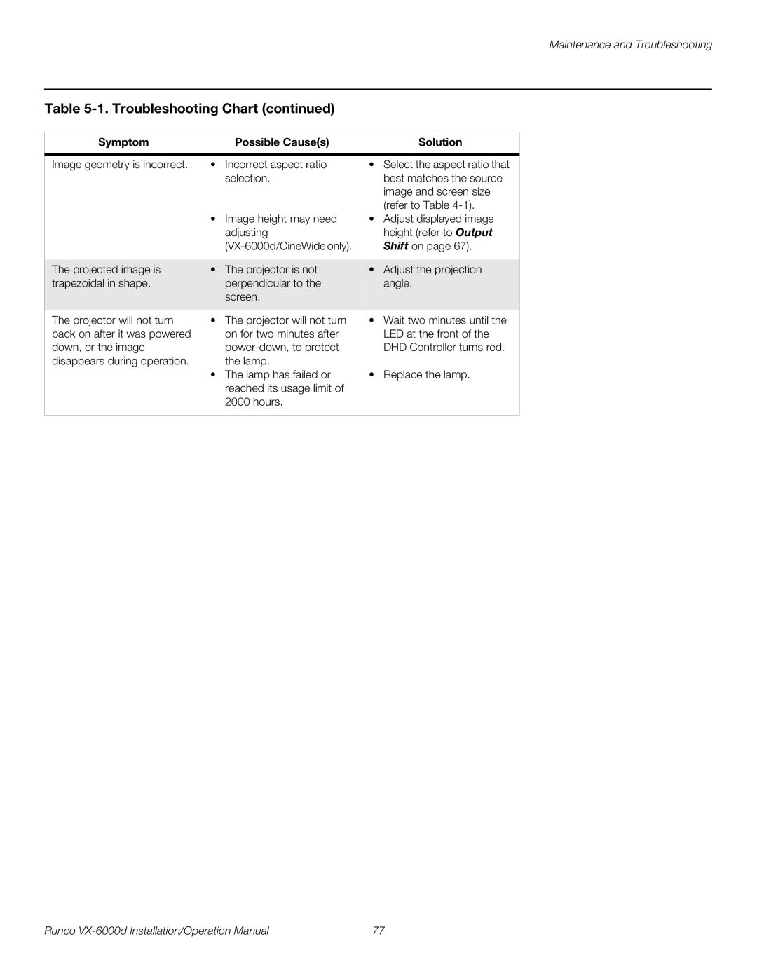
Table 5-1. Troubleshooting Chart (continued)
Symptom | Possible Cause(s) |
| Solution |
|
|
| |
Image geometry is incorrect. | • Incorrect aspect ratio | • Select the aspect ratio that | |
| selection. |
| best matches the source |
|
|
| image and screen size |
|
|
| (refer to Table |
| • Image height may need | • | Adjust displayed image |
| adjusting |
| height (refer to Output |
|
| Shift on page 67). | |
|
|
|
|
The projected image is | • The projector is not | • | Adjust the projection |
trapezoidal in shape. | perpendicular to the |
| angle. |
| screen. |
|
|
|
|
| |
The projector will not turn | • The projector will not turn | • Wait two minutes until the | |
back on after it was powered | on for two minutes after |
| LED at the front of the |
down, or the image |
| DHD Controller turns red. | |
disappears during operation. | the lamp. |
|
|
| • The lamp has failed or | • | Replace the lamp. |
| reached its usage limit of |
|
|
| 2000 hours. |
|
|
|
|
|
|
Runco | 77 |