Operation
Table 4-1. Aspect Ratio Settings (continued)
| Remote |
|
|
| ||
Aspect Ratio | Control | Description | ||||
| Button |
|
|
| ||
|
|
|
|
|
|
|
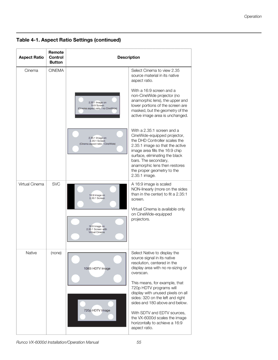
Cinema | CINEMA |
|
| Select Cinema to view 2.35 | ||
|
|
|
|
|
| source material in its native |
|
|
|
|
|
| aspect ratio. |
|
|
|
|
|
| With a 16:9 screen and a |
|
|
|
|
|
| |
|
|
|
|
| ||
|
|
| 2.35:1 Image on |
|
| anamorphic lens), the upper and |
|
|
|
|
| lower portions of the screen are | |
|
|
| 16:9 Screen |
|
| |
|
|
| (Cinema aspect ratio / no CineWide) |
|
| masked, but the geometry of the |
|
|
|
|
|
| |
|
|
|
|
|
| active image area is unchanged. |
|
|
|
|
| ||
|
|
|
|
|
| With a 2.35:1 screen and a |
|
|
|
|
|
| |
|
|
| 2.35:1 Image on |
|
| |
|
|
|
|
| the DHD Controller scales the | |
|
|
| 2.35:1 Screen |
|
| |
|
|
| (Cinema aspect ratio / CineWide) |
|
| 2.35:1 image so that the active |
|
|
|
|
|
| |
|
|
|
|
|
| image area fills the 16:9 chip |
|
|
|
|
|
| surface, eliminating the black |
|
|
|
|
|
| bars. The secondary, |
|
|
|
|
|
| anamorphic lens then restores |
|
|
|
|
|
| the proper geometry to the |
|
|
|
|
|
| 2.35:1 image. |
|
|
|
|
|
|
|
Virtual Cinema | SVC |
|
|
| A 16:9 image is scaled | |
|
|
| ||||
|
|
|
|
|
| |
|
|
| 16:9 IImage on |
|
| than in the center) to fit a 2.35:1 |
|
|
| 22..35:1 Screen |
|
| screen. |
|
|
|
|
|
| |
Virtual Cinema is available only on
16:9 Image on
2.35:1 Screen with
Virtual Cinema
Native | (none) |
| Select Native to display the |
| |||
|
|
| source signal in its native |
|
|
| resolution, centered in the |
|
| 1080i HDTV Image | display area with no |
|
|
| overscan. |
720p HDTV Image
This means, for example, that 720p HDTV programs will display with unused pixels on all sides: 320 on the left and right sides and 180 above and below.
With SDTV and EDTV sources, the
Runco | 55 |