Settings
Filter counter
This function is used to set a frequency for the filter replacement.
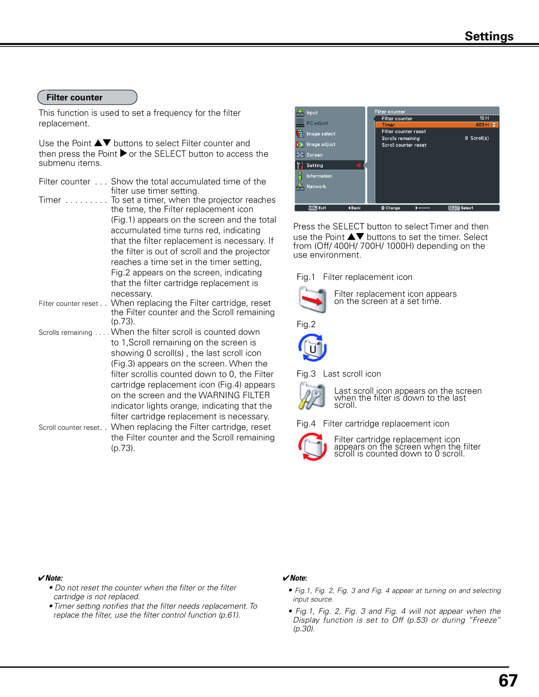
Use the Point ed buttons to select Filter counter and then press the Point 8or the SELECT button to access the submenu items.
Filter counter . . Show the total accumulated time of the filter use timer setting.
Timer . . . . . To set a timer, when the projector reaches the time, the Filter replacement icon (Fig.1) appears on the screen and the total accumulated time turns red, indicating that the filter replacement is necessary. If the filter is out of scroll and the projector reaches a time set in the timer setting, Fig.2 appears on the screen, indicating that the filter cartridge replacement is necessary.
Filter counter reset . When replacing the Filter cartridge, reset the Filter counter and the Scroll remaining (p.73).
Scrolls remaining . . When the filter scroll is counted down to 1,Scroll remaining on the screen is showing 0 scroll(s) , the last scroll icon (Fig.3) appears on the screen. When the filter scrollis counted down to 0, the Filter cartridge replacement icon (Fig.4) appears on the screen and the WARNING FILTER indicator lights orange, indicating that the filter cartridge replacement is necessary.
Scroll counter reset . When replacing the Filter cartridge, reset the Filter counter and the Scroll remaining (p.73).
Press the SELECT button to select Timer and then use the Point ed buttons to set the timer. Select from (Off/ 400H/ 700H/ 1000H) depending on the use environment.
Fig.1 Filter replacement icon
Filter replacement icon appears on the screen at a set time.
Fig.2
Fig.3 Last scroll icon
Last scroll icon appears on the screen when the filter is down to the last scroll.
Fig.4 Filter cartridge replacement icon
Filter cartridge replacement icon appears on the screen when the filter scroll is counted down to 0 scroll.
✔Note:
•Do not reset the counter when the filter or the filter cartridge is not replaced.
•Timer setting notifies that the filter needs replacement. To replace the filter, use the filter control function (p.61).
✔Note:
•Fig.1, Fig. 2, Fig. 3 and Fig. 4 appear at turning on and selecting input source.
•Fig.1, Fig. 2, Fig. 3 and Fig. 4 will not appear when the Display function is set to Off (p.53) or during “Freeze” (p.30).
67
