Introduction1/15
VDC-HD3300/HD300P VDC-HD3100/HD3100P
Introduction 2/15
HV/OFF
Introduction 3/15
Introduction 4/15
Introduction 5/15
Introduction 6/15
ASSIST/IRIS Settings
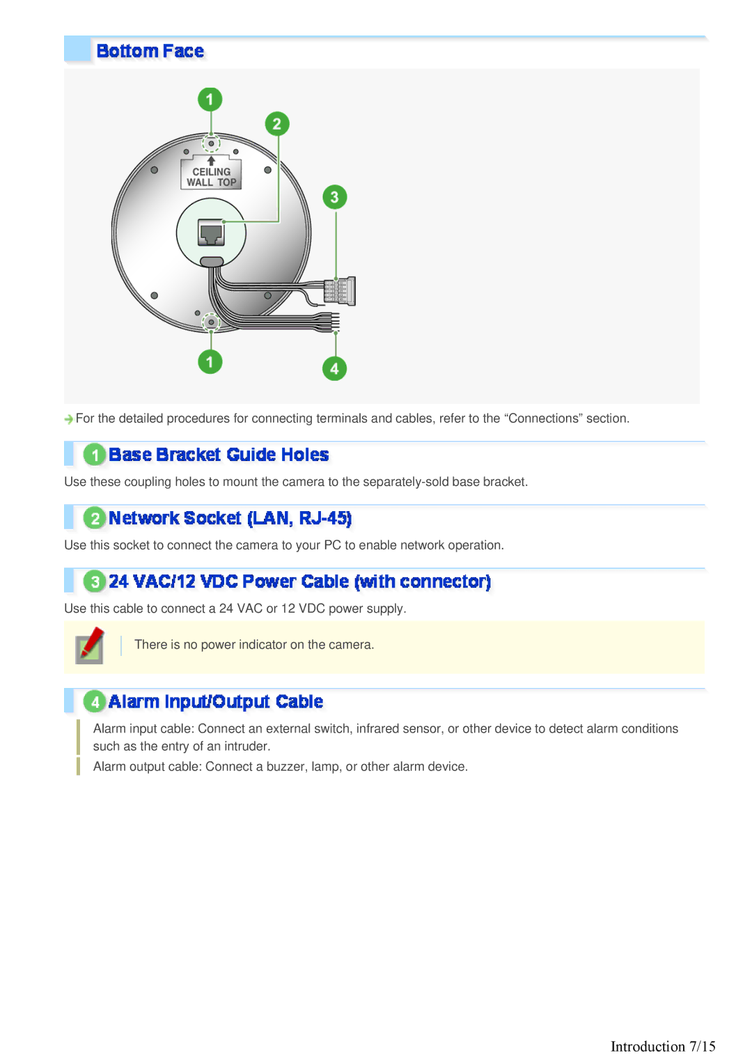
Introduction 7/15
Introduction 8/15
Alarm Input Terminal Connection
Introduction 9/15
Alarm Output Terminal Connection
Connection to 24 VAC power supply
Connection to 12 VDC power supply
Introduction 10/15
Using PoE
About the internet connection
Introduction 11/15
Press the SET button for 2 seconds or more
Introduction 12/15
Introduction 13/15
Adjusting focus
Introduction 14/15
Press the NEAR/FAR button to adjust the iris level
Introduction 15/15
Quick Operation Guide1/10
Turn on the camera
Connect the power cable to the power terminals
Connect the network LAN socket to your PC using a LAN cable
Quick Operation Guide 2/10
Quick Operation Guide 3/10
Access the camera from your PCs Web browser
Quick Operation Guide 4/10
Detect
Quick Operation Guide 5/10
Quick Operation Guide 6/10
Quick Operation Guide 7/10
Quick Operation Guide 8/10
Quick Operation Guide 9/10
Quick Operation Guide 10/10
Optional Configuration
Before You Begin Network Operation1/13
Monitor live video
Access the camera from your Web browser
Before You Begin Network Operation 2/13
Assign a unique IP address to each camera
Status
Before You Begin Network Operation 3/13
Before You Begin Network Operation 4/13
Click Auto IP Setup
Insert the supplied CD-ROM into the CD-ROM drive of your PC
Before You Begin Network Operation 5/13
Select the desired camera and click Manual setting
Make changes to the camera data and click Execute
Before You Begin Network Operation 6/13
Control Panel, click Network and Internet Connections
Before You Begin Network Operation 7/13
Click Network Connections
Click Properties
Before You Begin Network Operation 8/13
Control Panel, click Network and Sharing Center
Before You Begin Network Operation 9/13
Select the Internet Protocol Version 4 TCP/IPv4 check box
Before You Begin Network Operation 10/13
Click Manage network connections
Double-click Local Area Connection
Before You Begin Network Operation 11/13
Before You Begin Network Operation 12/13
Disabling authentication check at login
Before You Begin Network Operation 13/13
Working with Live Screen1/10
Working with Live Screen 2/10
Type your user name and password and click OK
Start Internet Explorer
Working with Live Screen 3/10
Working with Live Screen 4/10
Working with Live Screen 5/10
Menu Selection Buttons
Working with Live Screen 6/10
Other Buttons
Size
Working with Live Screen 7/10
Working with Live Screen 8/10
Click the Capture button on the tool panel
Working with Live Screen 9/10
Click Close
Automatic Stop
Starting alarm signal output
Stopping alarm signal output
Working with Live Screen 10/10
VDC-HD3300/HD300P VDC-HD3100/HD3100P
Working with Administrator Configuration Screens1/50
Working with Administrator Configuration Screens 2/50
IP ADDRESS, select Dhcp
Working with Administrator Configuration Screens 3/50
DDNS, select on
Working with Administrator Configuration Screens 4/50
Http PORT, type your Http port number
Working with Administrator Configuration Screens 5/50
Working with Administrator Configuration Screens 6/50
TITLE, type the desired camera title and click SET
Working with Administrator Configuration Screens 7/50
Clock DISPLAY, select the clock display style
Working with Administrator Configuration Screens 8/50
Working with Administrator Configuration Screens 9/50
Working with Administrator Configuration Screens 10/50
Anonymous User LOG IN, select on and click SET
Working with Administrator Configuration Screens 11/50
Configure the resolution Resolution
Working with Administrator Configuration Screens 12/50
Configure the image quality Picture Quality
Frame RATE, select the frame rate of the stream
Working with Administrator Configuration Screens 13/50
When your selection in Priority is Quality Picture Quality
When your selection in Priority is Bitrate Bitrate
Working with Administrator Configuration Screens 14/50
Configuration Summary for Each Sub Menu Item
Working with Administrator Configuration Screens 15/50
Sense UP, select the electronic sensitivity boosting power
Working with Administrator Configuration Screens 16/50
Configuring Monitoring Conditions
Switching between Monitoring Conditions
MASKING, select on and click SET
Working with Administrator Configuration Screens 17/50
Click SET and then Back
Working with Administrator Configuration Screens 18/50
White BALANCE, select AWC
Working with Administrator Configuration Screens 19/50
BLC, select Center and click SET
Working with Administrator Configuration Screens 20/50
Resize the center metering area
Click SET and then Back
Working with Administrator Configuration Screens 21/50
BLC, select Masking and click SET
Working with Administrator Configuration Screens 22/50
Working with Administrator Configuration Screens 23/50
Working with Administrator Configuration Screens 24/50
Manually Configuring Mode-Switching Luminance Level ADJ
Working with Administrator Configuration Screens 25/50
DAY/NIGHT, select Auto
Fixing Camera to Color Video Mode
Working with Administrator Configuration Screens 26/50
Fixing Camera to Black-and-White Video Mode
Vivid Color EFFECT, select on and click SET
Working with Administrator Configuration Screens 27/50
GAMMA, select the gamma correction level and click SET
DNR, select on and click SET
Working with Administrator Configuration Screens 28/50
Select the Manual check box
Click Privacy Mask in the sub menu
Working with Administrator Configuration Screens 29/50
MIRROR, select the desired mirror mode and click SET
Click ONE Push to focus on the subject
Select the Setting Items check box
Working with Administrator Configuration Screens 30/50
COLOR, select the color of the mask patterns
Working with Administrator Configuration Screens 31/50
Working with Administrator Configuration Screens 32/50
Working with Administrator Configuration Screens 33/50
SENSITIVITY, select the detection sensitivity
Working with Administrator Configuration Screens 34/50
Checking how the motion sensor works
Working with Administrator Configuration Screens 35/50
Working with Administrator Configuration Screens 36/50
Alarm
Working with Administrator Configuration Screens 37/50
Alarm OUT1, select Remote
Working with Administrator Configuration Screens 38/50
Configure your e-mail server
Working with Administrator Configuration Screens 39/50
To send a test e-mail, click Test
Working with Administrator Configuration Screens 40/50
AUTHENTICATION, select the authentication method
Mail ADDRESS, type the recipient e-mail addresses
If you selected Interval
Working with Administrator Configuration Screens 41/50
TRIGGER, select the e-mail transmission conditions
If you selected Network Failure
SUBJECT, type the subject title of the e-mail
Working with Administrator Configuration Screens 42/50
TEXT, type the message text and click SET
To use the passive FTP mode, in FTP PASSIVE, select USE
Working with Administrator Configuration Screens 43/50
To use a temporary file, set Temporary File to USE
Working with Administrator Configuration Screens 44/50
If you selected Alarm IN1/2, MOTION, or Alarm OUT1/2
Working with Administrator Configuration Screens 45/50
Working with Administrator Configuration Screens 46/50
Working with Administrator Configuration Screens 47/50
Select the firmware updater file
Working with Administrator Configuration Screens 48/50
Click SET
Working with Administrator Configuration Screens 49/50
Access LOG
Working with Administrator Configuration Screens 50/50
A1/10
2/10
Cannot access the camera
Camera has been suddenly disconnected
3/10
Buttons on the control panel/tool panel do not respond
4/10
Cannot set Shutter to Short or Long
5/10
Cannot display Live video
6/10
Video image is distorted and cannot be displayed correctly
7/10
Live video image is noisy
8/10
E-mail transmission function does not work
9/10
10/10
Upgrade has been terminated
Copyright Notice/How to Use This Manual1/8
Copyright Notice/How to Use This Manual 2/8
Copyright Notice/How to Use This Manual 3/8
Copyright Notice/How to Use This Manual 4/8
Title window
Index window
Main window
End
Previous/Next
123
3 ... a B C
Copyright Notice/How to Use This Manual 8/8