Hardware setup
Connection to the Modbus base port
8........................1 |
1
2
3
4
5
6
7
8
Not connected Not connected Not connected D1
D0
Not connected VP (1) Common
(1) Reserved for RS232/RS485 converter
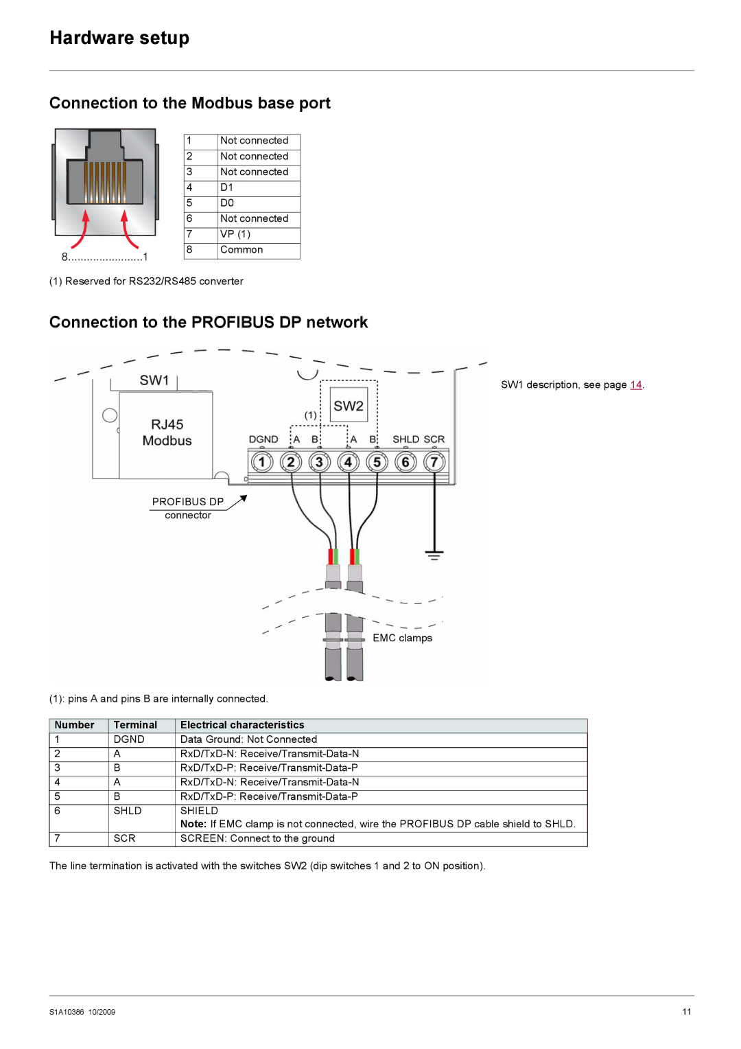
Connection to the PROFIBUS DP network
SW1 description, see page 14.
PROFIBUS DP
connector
EMC clamps
(1): pins A and pins B are internally connected.
Number | Terminal | Electrical characteristics |
1 | DGND | Data Ground: Not Connected |
2 | A | |
3 | B | |
4 | A | |
5 | B | |
6 | SHLD | SHIELD |
|
| Note: If EMC clamp is not connected, wire the PROFIBUS DP cable shield to SHLD. |
7 | SCR | SCREEN: Connect to the ground |
The line termination is activated with the switches SW2 (dip switches 1 and 2 to ON position).
S1A10386 10/2009 | 11 |