PROFIBUS DP mapping
Output PZDs
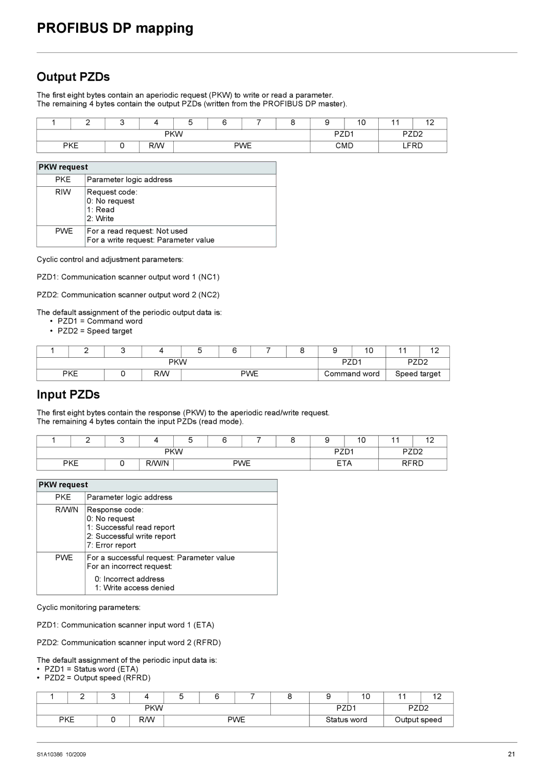
The first eight bytes contain an aperiodic request (PKW) to write or read a parameter. The remaining 4 bytes contain the output PZDs (written from the PROFIBUS DP master).
1 |
| 2 | 3 | 4 |
| 5 | 6 |
| 7 | 8 | 9 |
| 10 | 11 |
| 12 | |
|
|
|
| PKW |
|
|
|
|
|
| PZD1 |
|
| PZD2 | |||
|
|
|
|
|
|
|
|
|
|
|
|
|
| ||||
PKE |
| 0 | R/W |
|
|
| PWE |
|
| CMD |
|
| LFRD | ||||
|
|
|
|
|
|
|
|
|
|
|
|
|
|
|
|
|
|
PKW request |
|
|
|
|
|
|
|
|
|
|
|
|
|
|
| ||
PKE | Parameter logic address |
|
|
|
|
|
|
|
|
|
|
|
| ||||
|
|
|
|
|
|
|
|
|
|
|
|
|
|
|
| ||
RIW | Request code: |
|
|
|
|
|
|
|
|
|
|
|
|
|
| ||
0:No request
1:Read
2:Write
PWE | For a read request: Not used |
| For a write request: Parameter value |
Cyclic control and adjustment parameters:
PZD1: Communication scanner output word 1 (NC1)
PZD2: Communication scanner output word 2 (NC2)
The default assignment of the periodic output data is:
•PZD1 = Command word
•PZD2 = Speed target
1 | 2 | 3 | 4 | 5 | 6 | 7 | 8 | 9 | 10 | 11 | 12 |
|
|
| PKW |
|
|
|
|
| PZD1 |
| PZD2 |
| PKE | 0 | R/W |
|
| PWE |
| Command word | Speed target | ||
Input PZDs
The first eight bytes contain the response (PKW) to the aperiodic read/write request.
The remaining 4 bytes contain the input PZDs (read mode).
1 |
| 2 | 3 |
| 4 |
| 5 | 6 |
| 7 | 8 | 9 |
| 10 | 11 |
| 12 |
|
|
|
|
| PKW |
|
|
|
|
| PZD1 |
|
| PZD2 | |||
|
|
|
|
|
|
|
|
|
|
|
|
|
| ||||
PKE |
| 0 |
| R/W/N |
|
|
| PWE |
| ETA |
|
| RFRD | ||||
|
|
|
|
|
|
|
|
|
|
|
|
|
|
|
|
|
|
PKW request |
|
|
|
|
|
|
|
|
|
|
|
|
|
|
| ||
PKE | Parameter logic address |
|
|
|
|
|
|
|
|
|
|
| |||||
|
|
|
|
|
|
|
|
|
|
|
|
|
|
| |||
R/W/N | Response code: |
|
|
|
|
|
|
|
|
|
|
|
|
| |||
0:No request
1:Successful read report
2:Successful write report
7:Error report
PWE | For a successful request: Parameter value |
| For an incorrect request: |
0:Incorrect address
1:Write access denied
Cyclic monitoring parameters:
PZD1: Communication scanner input word 1 (ETA)
PZD2: Communication scanner input word 2 (RFRD)
The default assignment of the periodic input data is:
•PZD1 = Status word (ETA)
•PZD2 = Output speed (RFRD)
1 | 2 | 3 | 4 | 5 | 6 | 7 | 8 | 9 | 10 | 11 | 12 |
|
|
| PKW |
|
|
|
|
| PZD1 |
| PZD2 |
| PKE | 0 | R/W |
|
| PWE |
| Status word | Output speed | ||
S1A10386 10/2009 | 21 |